Hole-punching mold

A punching punch and punching technology, applied in the field of stamping devices, can solve problems such as complex molds, and achieve the effect of simple structure and convenient use

Inactive Publication Date: 2017-01-11
ANHUI JIANGHUAI AUTOMOBILE GRP CORP LTD
View PDF7 Cites 6 Cited by
  • Summary
  • Abstract
  • Description
  • Claims
  • Application Information

AI Technical Summary

Problems solved by technology

[0005] The invention provides a punching die, in order to solve the problem that the die is relatively complicated when punching a few-shaped parts in the prior art

Method used


Image

  • Hole-punching mold
  • Hole-punching mold
  • Hole-punching mold

Examples


Embodiment Construction

[0023] In order to enable those skilled in the art to better understand the technical solutions of the present invention, the present invention will be further described in detail below in conjunction with the accompanying drawings.

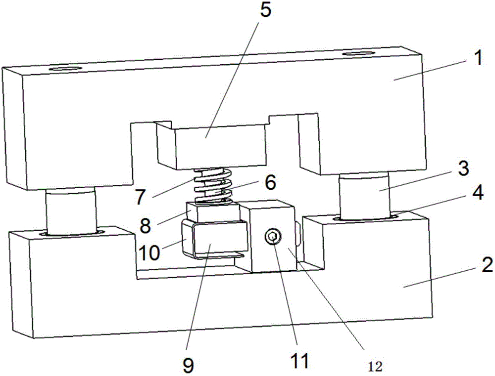
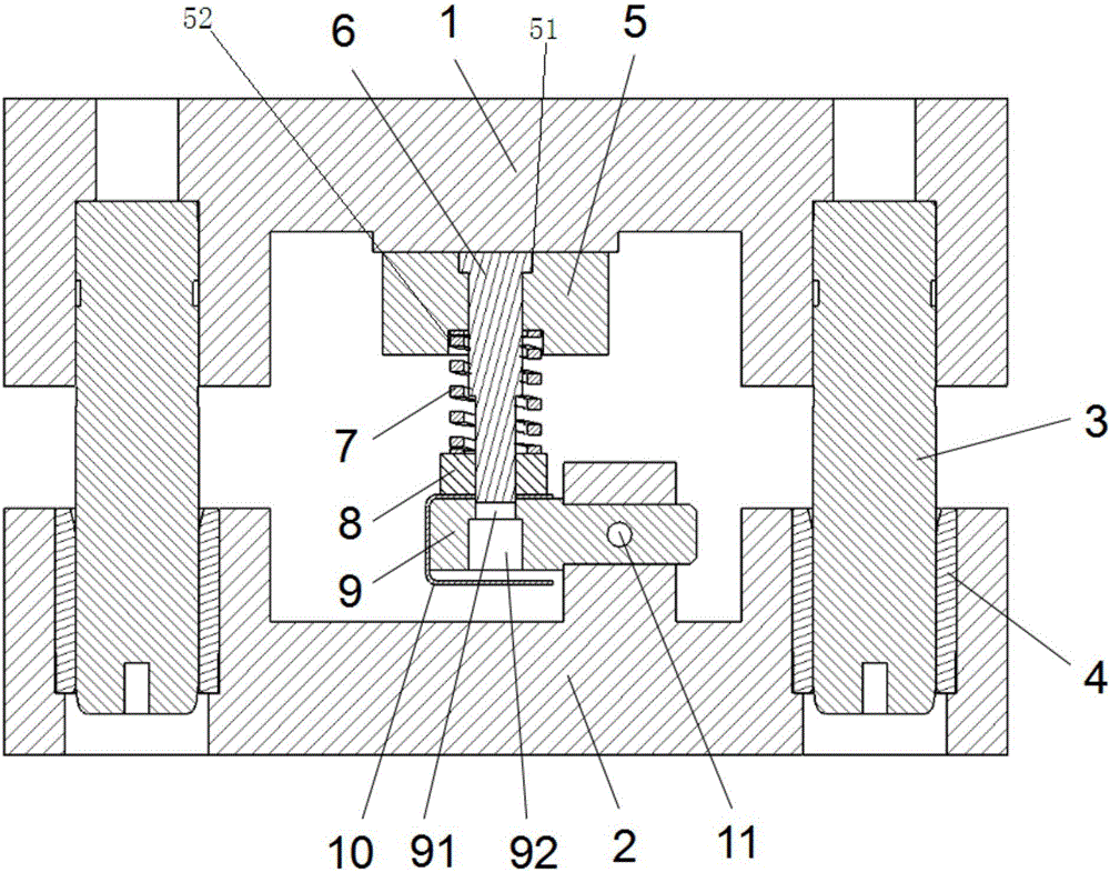
[0024] Such as Figure 2-4 As shown, a punching die provided by the embodiment of the present invention is used for punching several-shaped parts, and it specifically includes:

[0025] Lower mold base 2, which is used to carry the punched part 10;

[0026] Upper die base 1, which is used to drive the punching punch 9 to cooperate with the punching die 9 to realize the punching of the punched part 10, wherein the punched part is a several-shaped part;

[0027] Upper fixing block 5, which is fixed on the bottom surface of upper mold base 1;

[0028] The lower fixed block 12 is installed on the top surface of the lower mold base 2;

[0029] Punching die 9, the punching die 9 extends horizontally along the middle part of the lower fixed block 12,...


PUM


Abstract

The invention discloses a hole-punching mold. The U-shaped parts punching include lower die base and upper die base. The fixed block is fixed at the bottom of upper die base and the lower fixed block is installed on the top of the lower die base. The piercing die extends outside along the middle of the lower fixed block. There is one location hole longitudinally set on the piercing die. The hole-piercing punch is vertically set by directly facing the location hole at the bottom of the upper fixed block. The hole-piercing punch is of cylindrical structure matched with the location hole. In the invention, several U-shaped parts match with piercing die. The upper die base moves downwards, the hole-piercing punch goes through punched parts and location hole successively, thus punching U-shaped parts. The device is of simple structure and can be used easily.

Description

technical field [0001] The invention relates to the field of stamping devices, in particular to a punching die. Background technique [0002] In the production process of stamping parts, when the parts need to be punched, a pair of punching dies need to be designed separately to complete the processing of the holes on the parts. The traditional punching die structure includes upper die base, pressing core, punch, punching die, lower die base, etc. When encountering a shape such as figure 1 For semi-closed parts with the word "几", when the punching position is on the side wall of the part, side punching processing is required, and a wedge device is added, which makes the structure of the punching die complex, and the difficulty of installation and debugging increases. The time period grows. Especially when the hole size of some parts needs to be changed in design, punches and punching dies need to be processed, and repeated research and processing are required. [0003] Th...

Claims


Application Information

Patent Timeline
IPC IPC(8): B21D28/34B21D28/32
CPCB21D28/34B21D28/32
Inventor 徐肖黄涛徐鹏高双明井芊李杭
Owner ANHUI JIANGHUAI AUTOMOBILE GRP CORP LTD
Why Eureka
Try Eureka