Resonant sound
A technology of resonant sound and resonant sheet, applied in the direction of frequency/direction characteristic device, etc., can solve the problems of poor mid-range and mid-bass effect, high energy consumption, high cost, and achieve the improvement of mid-frequency and mid-low frequency effect, and high-frequency effect. simple structure
- Summary
- Abstract
- Description
- Claims
- Application Information
AI Technical Summary
Problems solved by technology
Method used
Image

Examples
no. 1 example
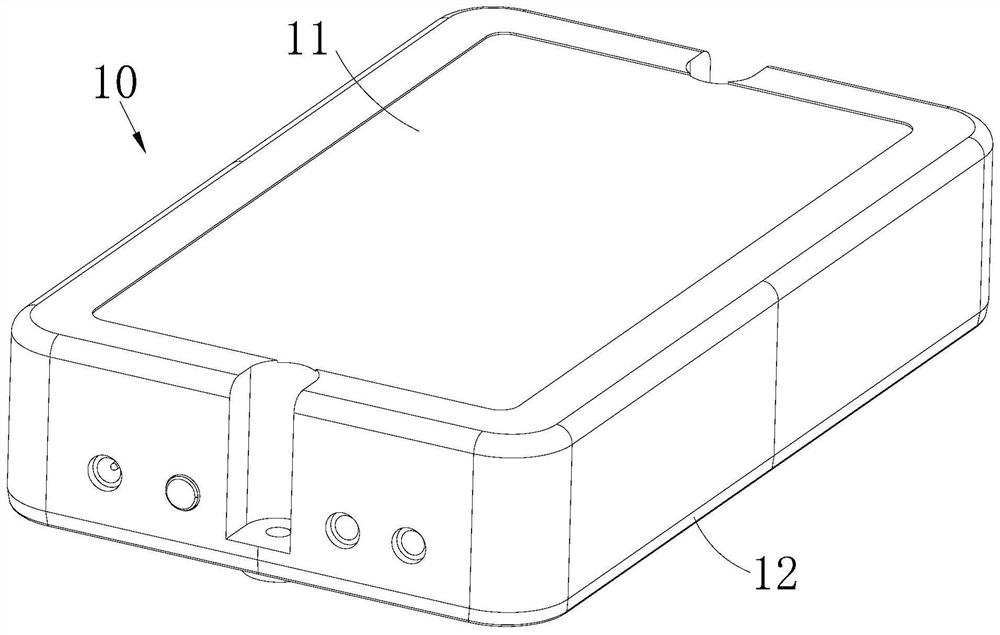
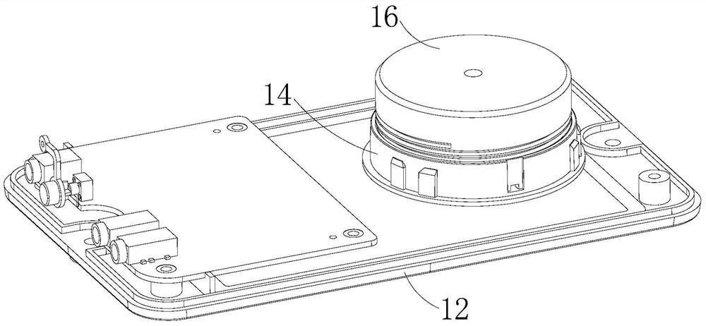
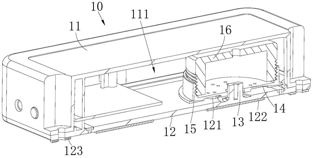
[0039] like Figure 1 to Figure 3 As shown, the resonance sheet 12 has a center (not shown in the figure), and the iron core post 13 , the sound plate 14 , the voice coil 15 and the vibrator 16 are arranged on the resonance sheet 12 away from the center of the resonance sheet 12 . In this way, when the resonant sound 10 resonates, the side of the resonant sheet 12 where the iron core column 13 is located off the center will have a smaller vibration amplitude than the opposite side, and the high-pitched effect will be better.
[0040] Of course, the iron core post 13 , the sound plate 14 , the voice coil 15 and the vibrator 16 can also be arranged on the center of the resonance sheet 12 .
no. 2 example
[0042] like Figure 4 and Figure 5 As shown, the sound cover 11b is provided with an air hole 112b for communicating with the outside and the resonance cavity 111b, and an air duct 113b for enhancing gas resonance extends inward from the hole wall of the air hole 112b. When the resonant cavity 111b resonates, the resonant gas inside it will convect with the outside through the air duct 113b and the air hole 112b, so that the resonance frequency of the resonant cavity 111b will be changed. Therefore, by adjusting the aperture size of the air hole 112b, or adjusting The length of the body of the air duct 113b is used to adjust the resonance frequency of the resonant cavity 111b, thereby increasing the mid-frequency and mid-low frequency.
[0043] finely, as Figure 4 and Figure 5 As shown, the resonance cavity 111b includes a left cavity 1111b and a right cavity 1112b, the iron core column 13b, the sound plate 14b, the voice coil 15b and the vibrator 16b are arranged in the r...
no. 3 example
[0046] like Image 6 and Figure 7 As shown, the sound cover 11c is provided with a first through groove 112c, and the first through groove 112c is provided with a diaphragm 113c for resonating with the sound cover 11c to enhance the mid-range and mid-bass. When the resonance cavity 111c resonates, the resonant gas inside will act on the diaphragm 113c to make the diaphragm 113c vibrate.
[0047] finely, as Image 6 and Figure 7 As shown, the resonance cavity 111c includes a left cavity 1111c and a right cavity 1112c, the iron core column 13c, the sound plate 14c, the voice coil 15c and the vibrator 16c are arranged in the right cavity 1112c, and the diaphragm 113c is arranged on the top of the sound cover 11 and located in the in the left cavity 1111c. Since the vibration amplitude of the resonance plate 12c located in the left cavity 1111c is larger than that of the resonance plate 12c located in the right cavity 1112c, the gas in the left cavity 1111c also has a larger...
PUM
 Abstract
Description
Claims
Application Information
 - R&D
- Intellectual Property
- Life Sciences
- Materials
- Tech Scout
- Unparalleled Data Quality
- Higher Quality Content
- 60% Fewer Hallucinations
Browse by: Latest US Patents, China's latest patents, Technical Efficacy Thesaurus, Application Domain, Technology Topic, Popular Technical Reports.
© 2025 PatSnap. All rights reserved.Legal|Privacy policy|Modern Slavery Act Transparency Statement|Sitemap|About US| Contact US: help@patsnap.com