


Quick Research
Generate reliable direction feasibility study reports for your R&D in just a few steps.

Technical Q&A
Discover and master advanced knowledge NOW. Basics, ideas, possibilities, all at once.

Find Solutions
As an expert in R&D theories, this can generate solutions to your technical problems instantly.

Evaluate Feasibility
Analyze your overall solution with one click, know your potential R&D risks in advance.

Monitor Landscape
Get weekly tech updates, stay abreast of the latest tech innovations and key insights.
High security anti-leakage magnetic motor rotor
A motor rotor, high-safety technology, applied in the direction of magnetic circuit rotating parts, electromechanical devices, electrical components, etc., can solve the problems of large motor stray loss, falling off motor operation, motor heating, etc., to improve safety and reliability, The effect of improving strength and rigidity and avoiding motor damage
- Summary
- Abstract
- Description
- Claims
- Application Information
AI Technical Summary
Problems solved by technology
Method used
Image

Examples
Embodiment 1
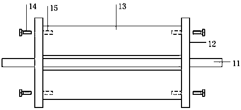
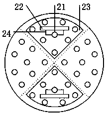
[0019] like figure 1 , figure 2 , image 3 As shown, the structure of the present invention includes a rotor core 13, a rotating shaft 11, a rotor end plate 12, a hinged hole bolt 14, a pressure-sensitive gasket 23, and a winding; the winding is wound on the rotor core 13; the rotor The iron core 13 is fixed on the rotating shaft 11, and it includes 4 fan-shaped solid magnetic pole cores. The rotor end plate 11 and hinged hole bolts 14 are all made of non-magnetic materials. The two ends of the fan-shaped solid magnetic pole cores have A plurality of hinged holes 15; the rotor end plate 12 is embedded with two pressure-sensitive gaskets 23, and the two pressure-sensitive gaskets 23 are center-symmetrical to the shaft hole in the center of the rotor end plate 12, and Each pressure-sensitive pad 23 corresponds to a fan-shaped solid magnetic pole core; there are several screw hole areas on the rotor end plate 12, wherein each screw hole area corresponds to a fan-shaped solid m...
Embodiment 2
[0026] The invention is used for a three-phase permanent magnet synchronous motor with a rated power of 500kw, a rated voltage of 6000v, a rated current of 51.6A, a frequency of 50HZ and a rotating speed of 1000 rpm. The outer diameter of the rotor fan-shaped solid magnetic pole core is Φ500mm, the inner diameter of the rotor fan-shaped solid magnetic pole core (the outer diameter of the magnetic isolation sleeve) is Φ280mm, and the length of the iron core is 590mm.
[0027] The rotor end plate is made of non-magnetic material stainless steel with a thickness of 15mm. The hinged hole bolts are made of non-magnetic material stainless steel. The threaded part is M24, and the smooth part of the hinged hole is Φ25mm.
[0028] End plates and hinged hole bolts at both ends of the rotor core:
[0029] (1) The material is 304 stainless steel, the thickness of the end plate is 15mm, the smooth part of the hinged hole bolt is Φ25mm, and the quantity is 8 pieces. 304 stainless steel mat...
Embodiment 3
[0058] The method for determining the preset rated value in the first embodiment includes the following steps:
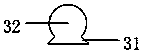
[0059] S1. Manufacture a semicircular mold consistent with the aperture size of the hinged hole 32 and have grooves consistent with the shape and size of the dovetail groove 31 on its wall;
[0060] S2. Fix the pressure-sensing sheet in the groove in the mold in step S1, connect the pressure-sensing sheet to the pressure sensing device 22, and connect the pressure sensing device 22 to an external receiving device;
[0061] S3. Use a hydraulic press to pressurize the inner wall of the semicircular mold described in step S1. The die of the hydraulic press is only in full contact with the pressure sensing plate. Stop pressurization during shear stress, and record the pressure value displayed by the external receiving device, which is the rated value; the pressure is calculated by the pressure applied by the hydraulic press and the extrusion area of the die of the hyd...
PUM
 Abstract
Description
Claims
Application Information
 - R&D Engineer
- R&D Manager
- IP Professional
- Industry Leading Data Capabilities
- Powerful AI technology
- Patent DNA Extraction
Browse by: Latest US Patents, China's latest patents, Technical Efficacy Thesaurus, Application Domain, Technology Topic, Popular Technical Reports.
© 2024 PatSnap. All rights reserved.Legal|Privacy policy|Modern Slavery Act Transparency Statement|Sitemap|About US| Contact US: help@patsnap.com