Display panel, manufacturing method thereof and display device

A technology for display panels and substrates, applied in the fields of display panels and display devices, can solve problems such as poor display brightness uniformity of displays, and achieve the effect of improving display brightness uniformity

Active Publication Date: 2017-01-04
BOE TECH GRP CO LTD
View PDF6 Cites 29 Cited by
  • Summary
  • Abstract
  • Description
  • Claims
  • Application Information

AI Technical Summary

Problems solved by technology

[0005] However, in the existing polymer-stabilized liquid crystal display, the light source module is a side-in type. As the distance between the pixel and the light source in the light source module increases, the light introduced into the area where the pixel is located gradually decreases, and the scattered light The display principle will also lead to the gradual reduction of the light imported into the area where the pixels are located, which will lead to poor uniformity of the display brightness of the display.

Method used


Image

  • Display panel, manufacturing method thereof and display device
  • Display panel, manufacturing method thereof and display device
  • Display panel, manufacturing method thereof and display device

Examples


example 1

[0052] Example 1: disposing the light absorbing layer outside the display panel.

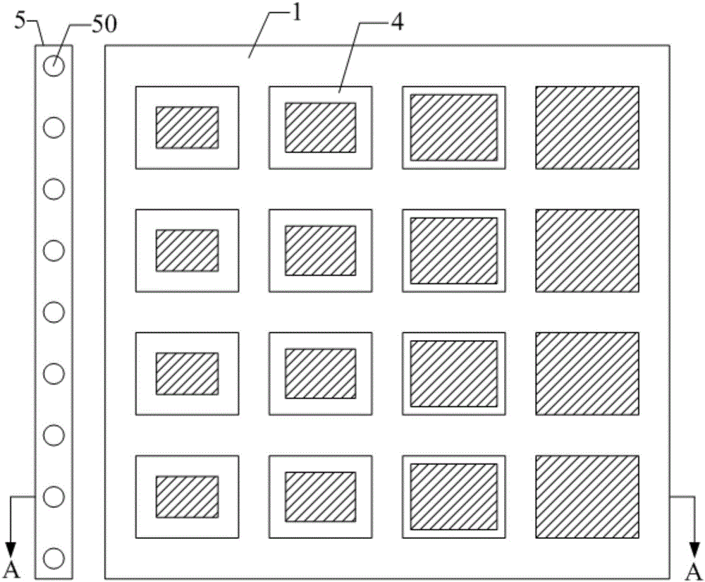
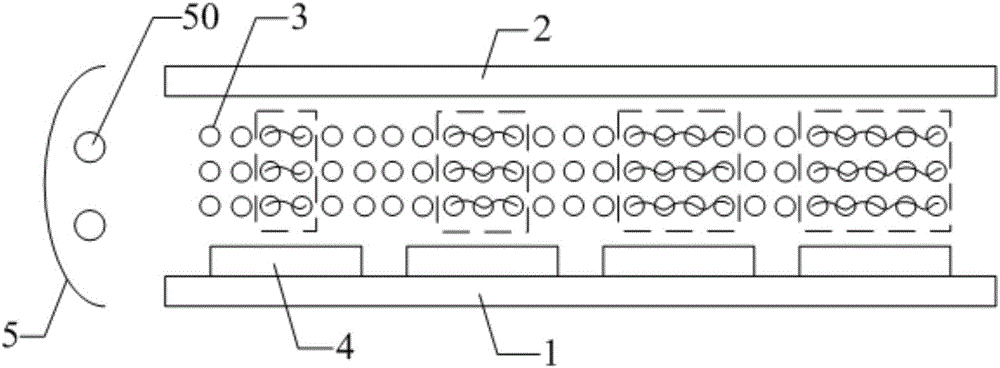
[0053] In specific implementation, in the above-mentioned display panel provided by the embodiment of the present invention, as Figure 4 As shown, the light absorbing layer 6 may include: a first light absorbing layer 61 located on the side of the first substrate 1 facing away from the liquid crystal layer 3 and a second light absorbing layer 62 located on the side of the second substrate 2 facing away from the liquid crystal layer 3 .

example 2

[0054] Example 2: disposing the light absorbing layer inside the display panel.

[0055] In specific implementation, in the above-mentioned display panel provided by the embodiment of the present invention, as Figure 5 and Figure 6 As shown, it may also include: a first alignment layer 7 on the side of the pixel 4 facing the liquid crystal layer 3 and a second alignment layer 8 on the side of the second substrate 2 facing the liquid crystal layer 3; preferably, in order to avoid affecting the liquid crystal molecules normal alignment, the light absorbing layer 6 cannot be arranged between the first alignment layer 7 and the liquid crystal layer 3 and between the second alignment layer 8 and the liquid crystal layer 3, but the light absorbing layer 6 is arranged on the first alignment layer 7 Between the first substrate 1 and between the second alignment layer 8 and the second substrate 2, that is, the light absorbing layer 6, such as Figure 5 and Figure 6 As shown, it m...


PUM

PropertyMeasurementUnit
visible light transmittanceaaaaaaaaaa

Abstract

The invention discloses a display panel, a manufacturing method thereof and a display device. In the display panel, liquid crystal molecules in a liquid crystal layer and in a region corresponding to each pixel are in a polymer network shape, and as the distance between the pixel and a light source in a lateral incoming light source module is larger, the area occupied by the polymer network formed through a photopolymerization reaction with the liquid crystal molecules in the region corresponding to each pixel is larger; in this way, when voltage is applied to each pixel, the outgoing light area of scattered light is larger and the outgoing light amount is larger due to disordered orientation caused by influence of the polymer network when the liquid crystal molecules in the region corresponding to the pixel farther away from the light source deflect, so that the problem that light introduced into the pixel region is less as the distance between the pixel and the light source is larger because of the lateral incoming light source module is solved. In this circumstance, the outgoing light amount of each pixel is controlled through adjustment of the effective outgoing light area of each pixel, and the uniformity of display brightness of the display panel can be effectively improved.

Description

technical field [0001] The invention relates to the field of display technology, in particular to a display panel, a manufacturing method and a display device. Background technique [0002] With the development of display technology, transparent display has gradually become a research hotspot in the field of display. At present, transparent displays are widely used in entertainment, security, transportation, power and other fields. [0003] In existing display devices, such as liquid crystal displays, organic electroluminescence displays, polymer dispersed liquid crystal displays, electrochromic displays, and electrowetting displays, there are various problems when applied to transparent displays. Among them, liquid crystal displays and organic electroluminescent displays have the problem of low light transmittance, generally below 40%; although the light transmittance of polymer dispersed liquid crystal displays, electrochromic displays and electrowetting displays meets th...

Claims


Application Information

Patent Timeline
Patent Type & Authority Applications(China)
IPC IPC(8): G02F1/1333G02F1/1343
CPCG02F1/133365G02F1/134309G02F1/1334G02F1/133615G02B6/00G02F1/13347G02F1/13345G02F1/13775H10K85/10G02F1/1333G02F1/13336G02F1/139
Inventor 王龙李延钊雎长城
Owner BOE TECH GRP CO LTD
Why Eureka
Try Eureka