
Airborne visual detecting and multi-target positioning system of unmanned gyroplane and implementation method

A multi-target positioning and realization method technology, applied in the field of positioning, navigation and control, can solve the problems of inability to locate multiple targets, the influence of signal transmission delay, and difficulty in meeting the use requirements

Active Publication Date: 2017-01-04
NANJING UNIV OF AERONAUTICS & ASTRONAUTICS
View PDF6 Cites 18 Cited by
  • Summary
  • Abstract
  • Description
  • Claims
  • Application Information

AI Technical Summary

Problems solved by technology

[0003] At present, there are mainly two forms of visual detection and target positioning system. One is that the visual processing part is set on the ground. After the airborne camera captures the target image, it transmits the image information back to the ground through radio, and the image processing computer on the ground calculates the target. The information is sent back to the UAV for use by the flight control system. This type of system has no restrictions on the power, volume, and processing capabilities of ground equipment, but it will be affected by signal transmission delays; the other is the setting of the visual processing part. On UAVs, this method avoids the time delay of transmitting information through radio, and greatly improves real-time performance and reliability. However, the airborne visual processing equipment is required to be small in size, light in weight, and the power should not be too large, which limits computing processing. ability
From the perspective of visual processing algorithms, in the past, researches on visual detection and positioning at home and abroad were relatively more focused on single targets. However, the existing technology cannot perform multi-target positioning, and it is difficult to meet normal use requirements

Method used


Image

  • Airborne visual detecting and multi-target positioning system of unmanned gyroplane and implementation method
  • Airborne visual detecting and multi-target positioning system of unmanned gyroplane and implementation method
  • Airborne visual detecting and multi-target positioning system of unmanned gyroplane and implementation method

Examples


Embodiment Construction

[0048] The technical scheme of the present invention will be described in further detail below in conjunction with the accompanying drawings.

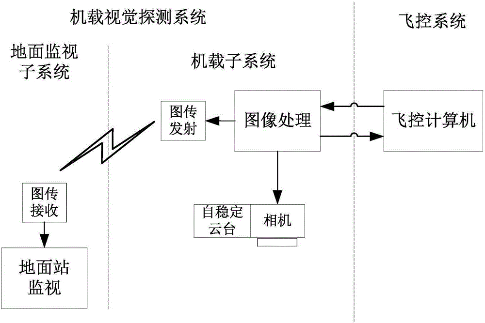
[0049] Such as figure 1As shown, the rotor UAV airborne visual detection and multi-target positioning system of the present invention is built on the Da Vinci series TMS320DM6437 processor as a platform, and consists of an airborne subsystem and a ground monitoring subsystem. The airborne subsystem includes a camera, a self-stabilizing gimbal, an image processing unit, and a video transmitter. The camera is installed on the self-stabilizing gimbal, and the self-stabilizing gimbal keeps the optical axis of the camera pointing to the ground and perpendicular to the ground. The image processing unit is connected to Image transmission transmitter. The image collected by the camera is transmitted to the image processing unit for processing, and then transmitted to the ground surveillance subsystem by the image transmission transmitter.

...


PUM


Abstract

The invention discloses an airborne visual detecting and multi-target positioning system of an unmanned gyroplane, and belongs to the technical field of positioning navigation and control. The system comprises an airborne subsystem and a ground monitoring subsystem; the airborne subsystem comprises a video collecting unit, an image processing unit and an image transmission transmitting terminal, and an image collected by the video collecting unit is processed by the image processing unit and then transmitted to the ground monitoring subsystem through the image transmission transmitting terminal; the ground monitoring subsystem comprises a ground station and an image transmission receiving terminal connected with the ground station, and the image transmission receiving terminal is communicated with the image transmission transmitting terminal. The system is compact in structure and achieves perfect integration with the unmanned gyroplane, flight and control of the unmanned gyroplane are convenient, therefore, the precision of target positioning is effectively guaranteed, and multi-target positioning is achieved. The invention further discloses an implementation method of the airborne visual detecting and multi-target positioning system of the unmanned gyroplane.

Description

technical field [0001] The invention relates to a dynamic positioning system, in particular to a rotary-wing UAV airborne visual detection and multi-target positioning system and an implementation method, belonging to the technical field of positioning navigation and control. Background technique [0002] Rotor UAV has the advantages of good maneuverability, hovering, vertical take-off and landing, and low cost. It has a very broad application prospect in military reconnaissance, power inspection, sea supply, crop protection, cargo handling and other fields. The airborne visual detection and target positioning system is an important part of the rotor UAV, and plays an important role in the mission of the rotor UAV. The vision system has the advantages of light weight, small size, low power consumption, high precision, and good concealment. Extensive research on the vision system of UAVs has been carried out at home and abroad, covering many fields such as target tracking, po...

Claims


Application Information

Patent Timeline
IPC IPC(8): G01C11/04
CPCG01C11/04
Inventor 张炳亮王彪徐锦法唐超颖
Owner NANJING UNIV OF AERONAUTICS & ASTRONAUTICS
Learn More