
Calculating method of equivalent pipe length of telescoping pipeline

A calculation method and technology of variable diameter tubes, applied in measuring devices, instruments, using ultrasonic/sonic/infrasonic waves, etc., can solve the problems of increased sound wave amplitude attenuation, inaccurate installation distance calculation, and leakage location errors, etc., to achieve Improve positioning accuracy, solve the effect of low positioning accuracy and convenient operation

Active Publication Date: 2017-01-04
CHINA UNIV OF PETROLEUM (EAST CHINA)
View PDF6 Cites 7 Cited by
  • Summary
  • Abstract
  • Description
  • Claims
  • Application Information

AI Technical Summary

Problems solved by technology

[0007] The existing patents are less involved in the calculation of the installation distance between the upstream and downstream sensors, and the improvement of the leak location accuracy relies more on the method of improving the sound wave propagation speed and time difference. There is no description of the change in the installation distance between them. The specific performance is: insufficient consideration of the reflection, secondary reflection and interference of the sound wave when the sound wave encounters the reducing tube during the propagation process, which makes the attenuation of the sound wave amplitude significantly increased. Large, so that the calculation of the installation distance between the upstream and downstream sensors is inaccurate, resulting in leakage positioning errors

Method used


Image

  • Calculating method of equivalent pipe length of telescoping pipeline
  • Calculating method of equivalent pipe length of telescoping pipeline
  • Calculating method of equivalent pipe length of telescoping pipeline

Examples


Embodiment Construction

[0034] The present invention will be further described below in conjunction with the accompanying drawings and embodiments.

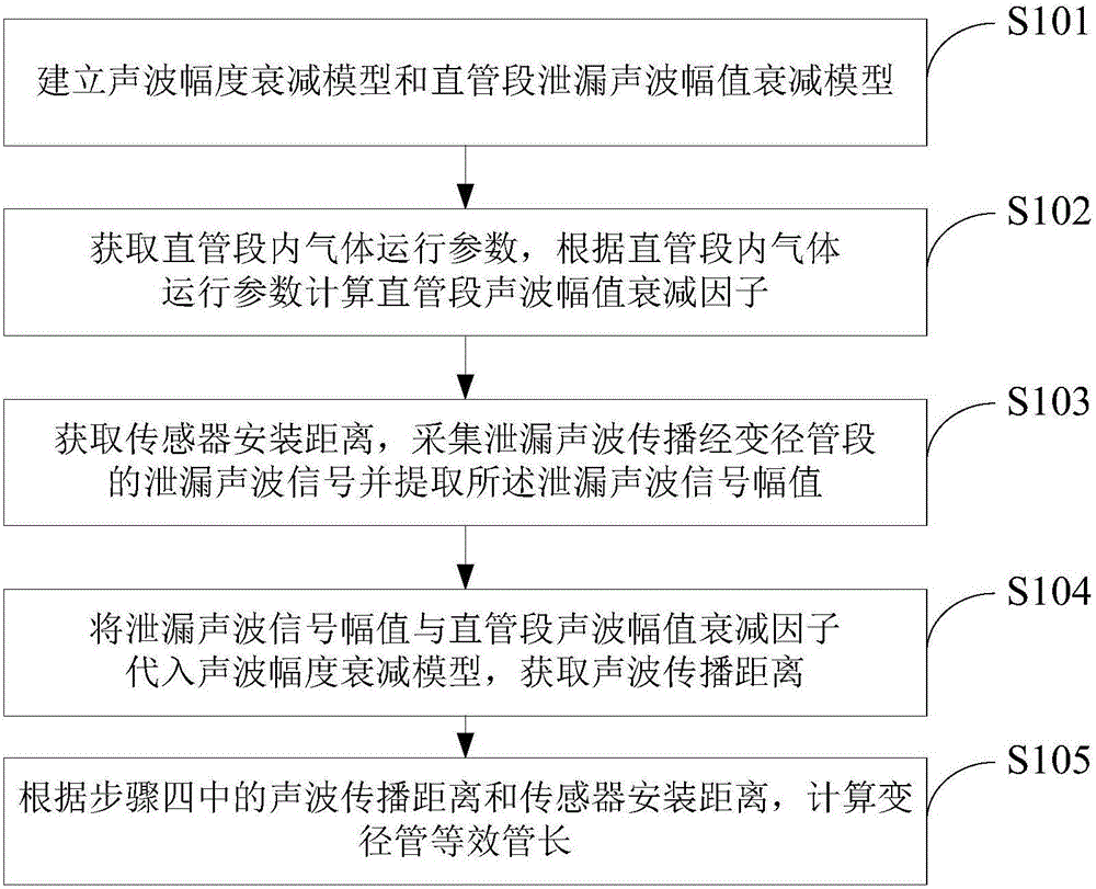
[0035] Such as figure 1 As shown, a calculation method for the equivalent length of a reducing pipe includes the following steps:

[0036] Step S101: Establish a sound wave amplitude attenuation model and a straight pipe leakage sound wave amplitude attenuation model;

[0037] Step S102: Obtain the gas operating parameters in the straight pipe section, and calculate the acoustic wave amplitude attenuation factor of the straight pipe section according to the gas operating parameters in the straight pipe section;

[0038] Step S103: Obtain the installation distance of the two sensors, collect the leakage acoustic wave signal of the leakage acoustic wave propagating through the variable diameter pipe section, and extract the amplitude of the leakage acoustic wave signal;

[0039] Step S104: Substituting the amplitude of the leaked acoustic signal and the...


PUM


Abstract

The invention discloses a calculating method of the equivalent pipe length of a telescoping pipeline. The method includes steps: establishing a sound wave amplitude attenuation model and a straight tube segment leakage sound wave amplitude attenuation model; obtaining gas operation parameters in a straight tube segment, and calculating a straight tube segment sound wave amplitude attenuation factor according to the gas operation parameters in the straight tube segment; obtaining an installation distance of two sensors, acquiring leakage sound wave signals of leakage sound waves spreading through a telescoping pipeline segment, and extracting a leakage sound wave signal amplitude; introducing the leakage sound wave signal amplitude and the straight tube segment sound wave amplitude attenuation factor into the sound wave amplitude attenuation model, and obtaining a sound wave spreading distance; and calculating the equivalent pipe length of the telescoping pipeline according to the sound wave spreading distance in step 4 and the installation distance of the two sensors in step 3. The beneficial effects of the calculating method of the equivalent pipe length of the telescoping pipeline are that the equivalent safety distance of the sensors can be obtained through the establishment of the calculating formula of the equivalent pipe length of the telescoping pipeline, and the positioning precision is improved.

Description

technical field [0001] The invention relates to the technical field of oil and gas pipeline leakage monitoring by acoustic wave method, in particular to a method for calculating the equivalent pipe length of a variable diameter pipe. Background technique [0002] At present, there are many leakage monitoring methods that can be applied to oil and gas pipelines. Among them, the acoustic wave method has many advantages compared with the traditional mass balance method, negative pressure wave method, and transient model method: high sensitivity, high positioning accuracy, and false alarms. Low rate, short detection time, strong adaptability; the measurement is the weak dynamic pressure change in the pipeline fluid, which has nothing to do with the absolute value of the pipeline operating pressure; the response frequency is wider, the detection range is wider, etc. [0003] In the research on the leakage detection and location technology of the gas pipeline acoustic method, the ...

Claims


Application Information

Patent Timeline
Patent Type & Authority Applications(China)
IPC IPC(8): G01B17/00
CPCG01B17/00
Inventor 李玉星刘翠伟耿晓茹韩金珂李万莉梁杰
Owner CHINA UNIV OF PETROLEUM (EAST CHINA)
Learn More