light emitting diode light emitting device

A technology of light-emitting diodes and light-emitting devices, which is applied to lighting devices, components of lighting devices, electric light sources, etc., and can solve problems such as poor conductive contact and low conductive efficiency

Inactive Publication Date: 2019-05-03
CAL COMP ELECTRONICS +1
View PDF4 Cites 0 Cited by
  • Summary
  • Abstract
  • Description
  • Claims
  • Application Information

AI Technical Summary

Problems solved by technology

When the conductive needle deviates too much from the center of the gap, the force applied by the jaws to hold the conductive needle will be insufficient, resulting in low conductive efficiency or poor conductive contact

Method used


Image

  • light emitting diode light emitting device
  • light emitting diode light emitting device
  • light emitting diode light emitting device

Examples


Embodiment Construction

[0056] The present invention will be further described below in conjunction with specific examples, so that those skilled in the art can better understand the present invention and implement it, but the given examples are not intended to limit the present invention.

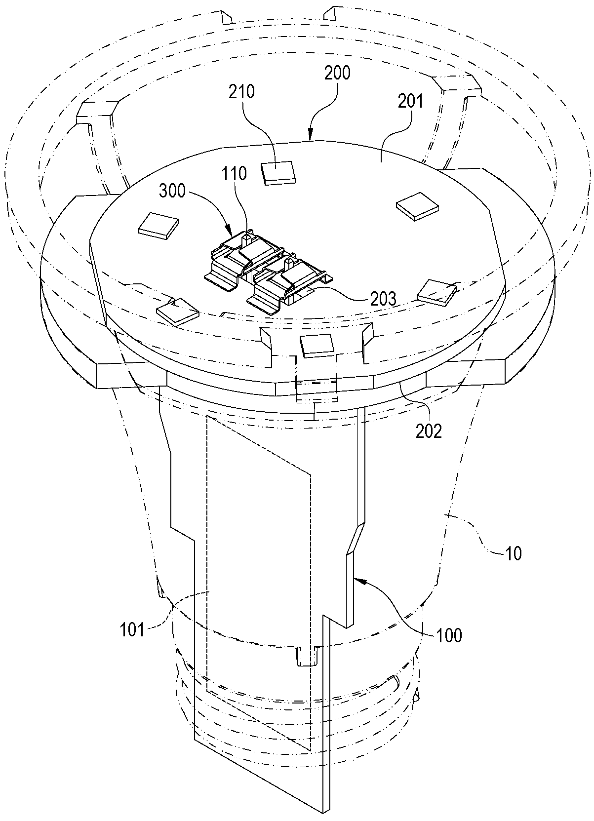
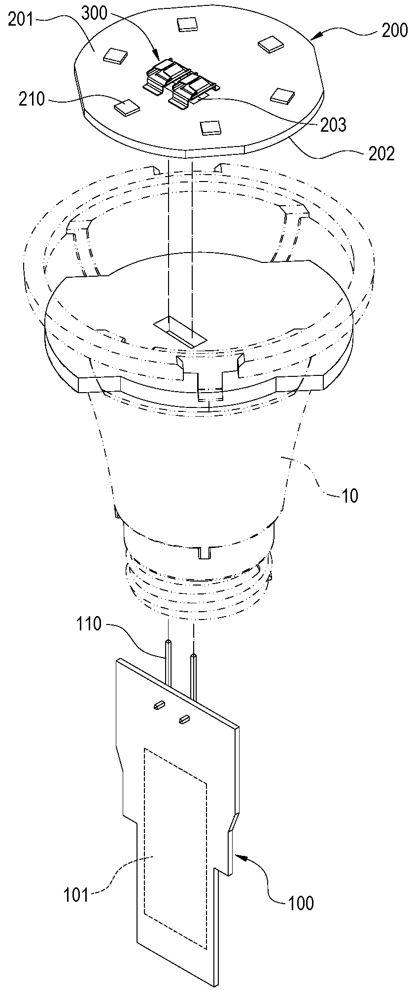
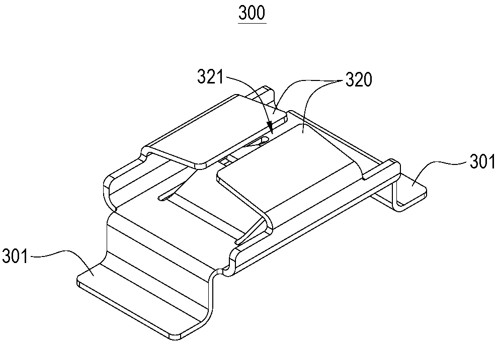
[0057] refer to figure 1 and figure 2 , the first embodiment of the present invention provides a light-emitting diode lighting device, which includes a lamp cup 10, a first circuit board 100, a second circuit board 200 and at least one conductive shrapnel 300, in this embodiment Preferably, a pair of guiding elastic pieces 300 is included, and the present invention does not limit the number of guiding elastic pieces 300 .

[0058] In this embodiment, the lamp cup 10 is preferably a cone, and the first circuit board 100 is accommodated in the lamp cup 10 and arranged along the longitudinal direction of the lamp cup 10 . A transformer circuit 101 is arranged on the first circuit board 100, and at least one condu...


PUM


Abstract

The invention discloses an LED illumination apparatus including a lamp housing, a first circuit board arranged in the lamp housing, a second circuit board arranged on the lamp housing and a conductive dome. A conductive pin is provided on the first circuit board. The second circuit board is arranged perpendicular with the first circuit board, and an opening is disposed on the second circuit board. The conductive dome is arranged in the second circuit board, and a through hole is disposed on the conductive dome. A couple of first claws are extended from an inner edge of the through hole, and a first gap is formed between the tail ends of the first claws. A couple of second claws are extended from an outer edge of the conductive dome, the second claws are respectively and reversely folded to face the through hole, and a second gap is formed between the tail ends of the second claws. The first gap and the second gap are arranged on non-parallel and corresponding to the opening. The conductive pin is extended through the opening. The conductive pin is inserted in the first gap, and thereby clamped by the first claws. Thereby, it is possible to restrict the position of the conductive pin in a different direction to achieve a multi-directional positioning function.

Description

technical field [0001] The invention relates to a light-emitting diode lighting device, in particular to a light-emitting diode lighting device with multi-directional positioning shrapnel. Background technique [0002] Most of the general light emitting diode bulbs are split into a light source module and a transformer module, which are manufactured with two circuit boards respectively. Therefore, when the light source module and the transformer module are assembled, they must be connected with a conductive component. A common connection method is achieved by inserting a conductive needle into a conductive shrapnel, and the conductive shrapnel forms a pair of jaws to hold the conductive needle. [0003] The disadvantage of the aforementioned structure is that the conductive needle is clamped in the gap between the jaws, and the conductive needle can still move along the gap. The conductive needles are clamped at different positions in the gap, and the forces applied by the...

Claims


Application Information

Patent Timeline
Patent Type & Authority Patents(China)
IPC IPC(8): F21V23/06F21V19/00F21S4/00
CPCF21V19/0005F21V23/06
Inventor 吴宪昌廖哲新欧春亨
Owner CAL COMP ELECTRONICS
Why Eureka
Try Eureka