Guid positioning probe

A technology for guiding positioning and probes, which is applied in the field of probes, and can solve problems such as affecting the conduction connection between external electronic components and probes, and prone to skewing and misalignment.

Pending Publication Date: 2019-01-15
DONGGUAN C C P CONTACT PROBES
View PDF0 Cites 0 Cited by
  • Summary
  • Abstract
  • Description
  • Claims
  • Application Information

AI Technical Summary

Problems solved by technology

[0004] However, during the process of the push pin shaft of the external electronic component sliding from the initial position to the compressed position, since the existing probe has no guiding and positioning structure, the external electronic component is prone to skew and deflection when docking with the probe, thus affecting the external Conductive connection of electronic components to probes

Method used


Image

  • Guid positioning probe
  • Guid positioning probe
  • Guid positioning probe

Examples


Embodiment Construction

[0023] In order to describe the technical content and structural features of the present invention in detail, further description will be given below in conjunction with the implementation and accompanying drawings.

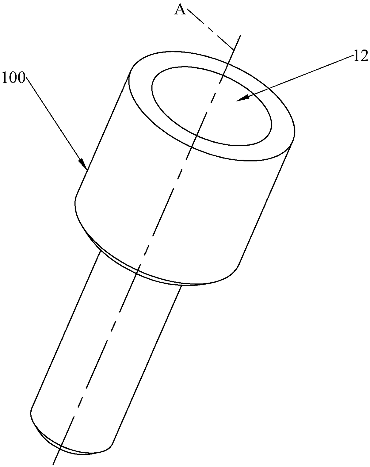
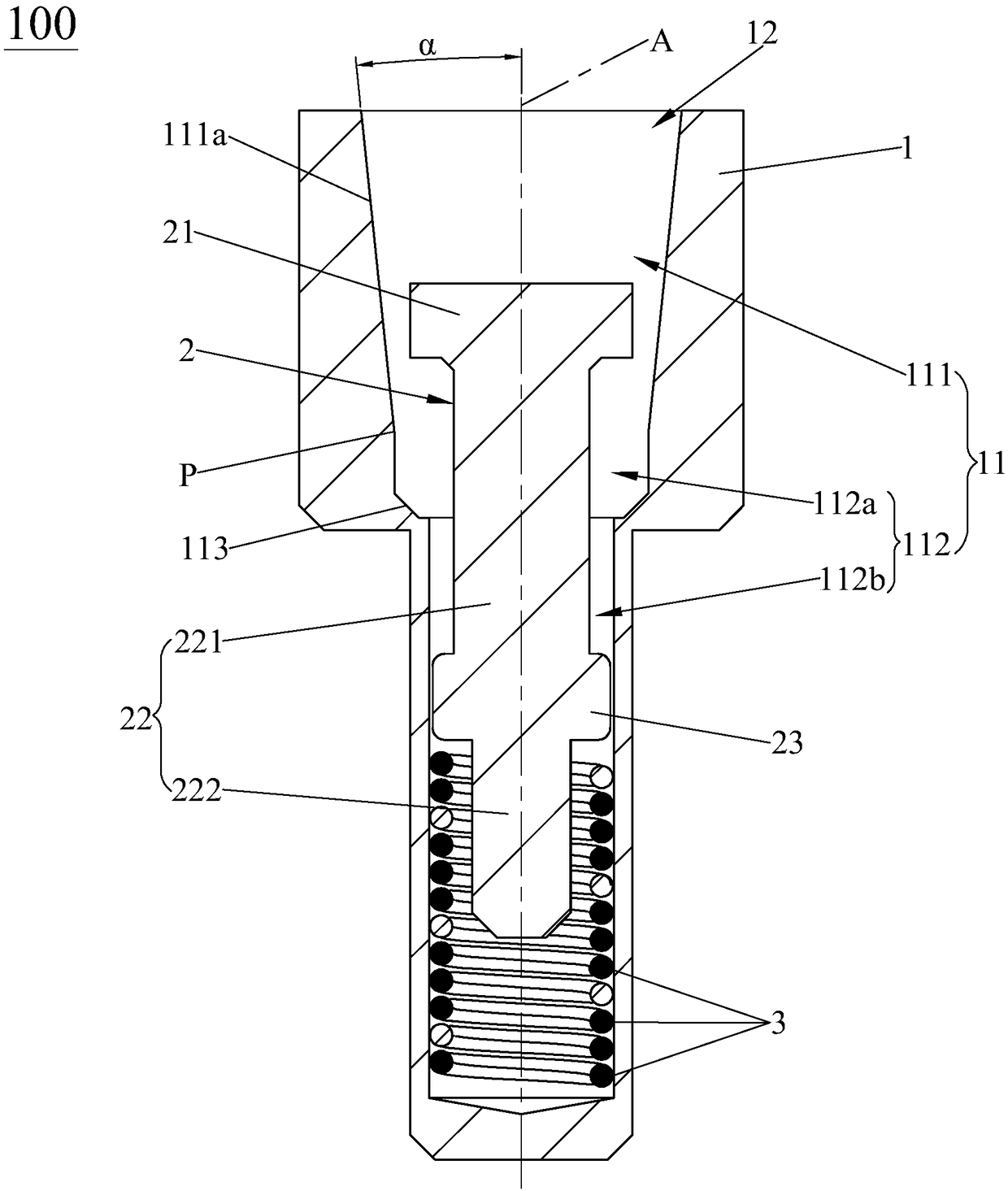
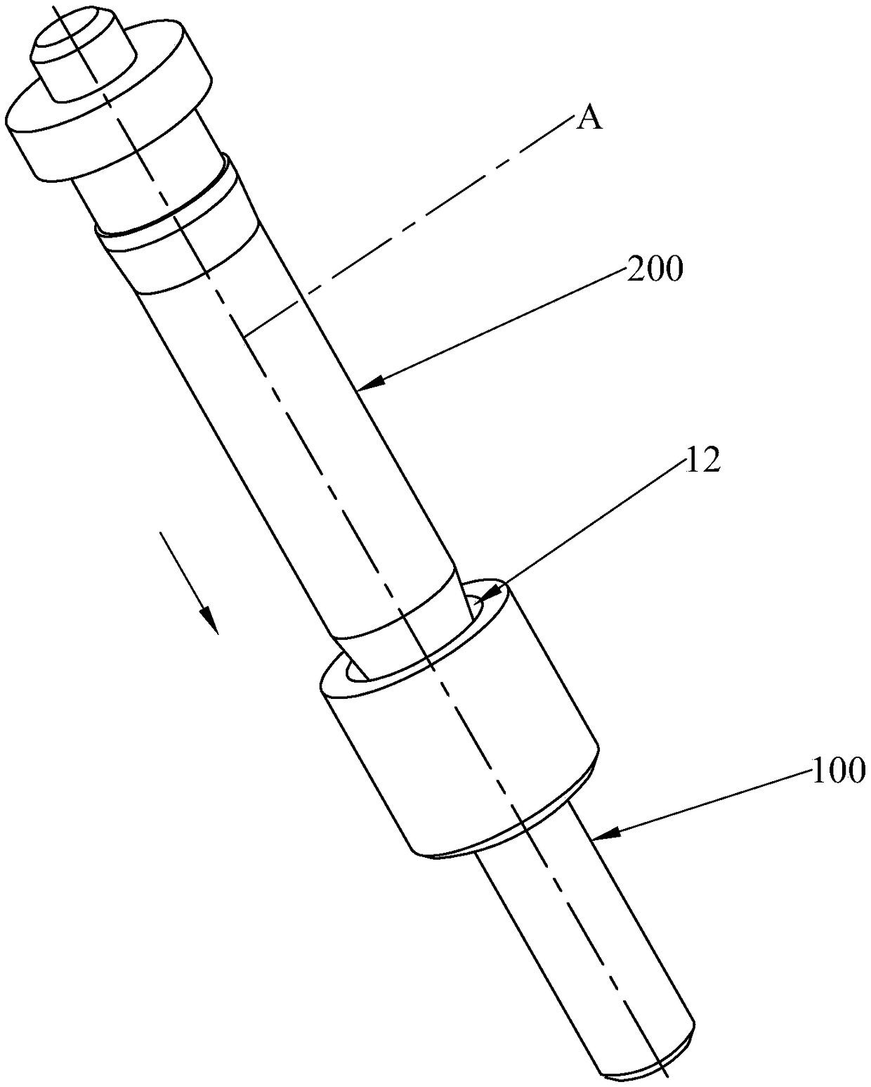
[0024] see Figure 1 to Figure 3 , the guiding and positioning probe 100 of the present invention includes a needle shaft 2 , a reset member 3 and a needle tube 1 with a receiving cavity 11 . The receiving cavity 11 penetrates the needle tube 1 forward along the axial direction of the needle shaft 2 to form a cavity 12. The needle shaft 2 is slidably sleeved in the receiving cavity 11 and has at least an initial position relative to the needle tube 1 (such as Figure 4 shown) and a compression position that slides backward along the axial direction of the needle shaft 2 (such as Figure 5 shown); the reset member 3 is located in the storage cavity 11 and is used to drive the needle shaft 2 to slide to the initial position. The storage cavity 11 includes a guide ...


PUM


Abstract

A guide positioning probe Including needle shaft, a reduction member and a needle tube having a receiving cavity, the receiving cavity penetrates the needle tube forward in the axial direction of theneedle shaft to form a lumen, A needle shaft is slidably sleeved in the receiving cavity and has at least an initial position and a compression position with respect to the needle tube, A reset memberis positioned in the receiving cavity and drives the needle shaft to slide to an initial position, The receiving cavity comprises a guide positioning cavity and a built-in cavity, wherein the guide positioning cavity is located in front of the built-in cavity, the radial dimension of the guide positioning cavity is gradually reduced rearward along the axial direction of the needle shaft, and whenthe needle shaft is located in the initial position, the needle shaft extends forward along the axial direction of the needle shaft and extends into or extends out of the guide positioning cavity. Therefore, the gap between the external electronic components and the inner wall of the guide and positioning cavity becomes smaller and smaller in the process of the external electronic components entering the guide and positioning cavity, so that the shaking range of the external electronic components is limited, the guide and positioning functions are achieved, and the deviation of the external electronic components during the docking process is prevented from affecting the conduction with the probe.

Description

technical field [0001] The invention relates to the field of probes, in particular to a guiding and positioning type probe. Background technique [0002] The probe is a precision connector, which is widely used in electronics, military industry, medical treatment, aerospace and other fields. With the development of science and technology and the progress of humanities, in order to meet people's increasing technological needs, correspondingly, the structure and technology of probes must be continuously improved. [0003] At present, a traditional probe includes a needle shaft, a needle tube, and a spring. The needle shaft is slidably sleeved in the accommodation chamber of the needle tube and has an initial position and a compressed position for sliding backward along the axial direction of the needle tube relative to the needle tube. The spring is located at the The housing cavity is elastically abutted between the needle shaft and the needle tube, so that the needle shaft ...

Claims


Application Information

Patent Timeline
Patent Type & Authority Applications(China)
IPC IPC(8): H01R13/24
CPCH01R13/2421
Inventor 蔡宗明漆高正陈威戎蔡伯晨
Owner DONGGUAN C C P CONTACT PROBES
Why Eureka
Try Eureka