
Electro-hydraulic apparatus

An electro-hydraulic and motor room technology, applied in valve devices, valve operation/release devices, valve details, etc., can solve problems such as manual intervention in valve systems, achieve accurate positioning, facilitate processing and assembly, and reduce failure rates. Effect

Inactive Publication Date: 2017-01-04
汉盛(上海)海洋装备技术股份有限公司
View PDF8 Cites 1 Cited by
  • Summary
  • Abstract
  • Description
  • Claims
  • Application Information

AI Technical Summary

Problems solved by technology

[0003] The purpose of the present invention is to provide an electro-hydraulic device for independently driving valves, which mainly solves the technical problem that manual intervention is required when the valve system fails

Method used


Image

  • Electro-hydraulic apparatus
  • Electro-hydraulic apparatus
  • Electro-hydraulic apparatus

Examples


Embodiment Construction

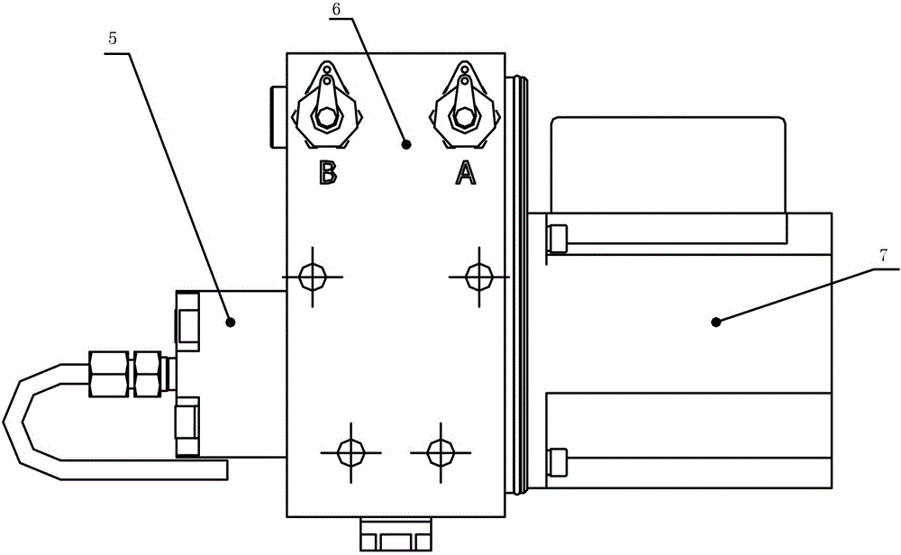
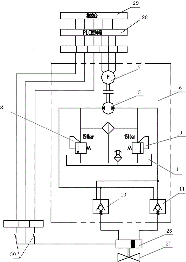
[0023] according to figure 1 , 2, 5, 6, 7, 8, 9, 10, 11, 12, an electro-hydraulic device, including an oil tank 1, a main structure 2 and a motor room 4 connected in sequence, and an electrical junction box 3 is arranged on one side of the motor room, The main structure 2 is composed of a two-way gear oil pump 5, an integrated control block assembly 6, and a motor 7; the output end of the oil tank 1 is connected to the two-way gear oil pump 5, and the four input ends of the oil tank are respectively equipped with a pressure adjustment device A8, a pressure adjustment device B9, Valve positioner A10 and valve positioner B11, pressure regulating device A8 communicates with valve positioner B11, pressure regulating device B9 communicates with valve positioner A10, two-way gear oil pump 5 is connected with motor 7 in two directions, and two-way gear oil pump 5 is also connected with pressure regulator The device A8, the pressure regulating device B9, the valve positioner A10 and t...


PUM


Abstract

The invention relates to a hydraulic valve remote control system for ships and ocean equipment, and particularly discloses an electro-hydraulic apparatus, which mainly solves the technical problem that a fault of a valve system needs manual intervention. According to the technical scheme, the electro-hydraulic apparatus comprises an oil tank, a main body structure and a motor chamber, which are successively connected, wherein one side of the motor chamber is provided with an electrical junction box, and the main body structure consists of a bidirectional gear oil pump, an integrated control block assembly and a motor; the output end of the oil tank is connected with the bidirectional gear oil pump, four input ends of the oil tank are respectively provided with a pressure adjusting apparatus A, a pressure adjusting apparatus B, a valve positioner A and a valve positioner B, the pressure adjusting apparatus A is communicated with the valve positioner B, the pressure adjusting apparatus B is communicated with the valve positioner A, the bidirectional gear oil pump is bidirectionally connected with the motor, and the bidirectional gear oil pump is also communicated with the pressure adjusting apparatus A, the pressure adjusting apparatus B, the valve positioner A and the valve positioner B. The electro-hydraulic apparatus is applied to an openness or switch-type rotary motion valve.

Description

technical field [0001] The invention relates to a hydraulic valve remote control system for ships and marine equipment, and in particular discloses an electro-hydraulic device, which is a device for independently providing pressure oil to each valve during the remote control of the valve. Background technique [0002] At present, the domestic hydraulic valve remote control system generally adopts the route from the hydraulic power unit, the solenoid valve box, the hydraulic driver to the valve to realize the remote control of the valve. This situation has some disadvantages: when the hydraulic power unit or the solenoid valve box fails, it may cause all valves in the entire system to be inoperable. The remedial measures that can be taken are generally manual operation with manual hydraulic pumps, and important valves are equipped with single-acting spring return drivers, etc. This will inevitably affect the automatic control of the valve, and even affect the safe operation ...

Claims


Application Information

Patent Timeline
Patent Type & Authority Applications(China)
IPC IPC(8): F16K31/04F16K31/12F16K37/00
CPCF16K31/04F16K31/12F16K37/0066
Inventor 顾耀民李军华陈亚军
Owner 汉盛(上海)海洋装备技术股份有限公司
Learn More