Three-dimensional shock-insulation device capable of presetting vertical early stiffness

A vertical seismic isolation, three-dimensional technology, applied in the direction of earthquake resistance, building components, building structures, etc., can solve the problems of reducing the cost of seismic isolation, shortening the effective working length of the spring, not being able to stretch, energy consumption and shock absorption, etc., to achieve buffer tension The impact of extension and compression, reducing the cost of wind and earthquake resistance, and reducing the risk of overturning

Pending Publication Date: 2017-01-04
ANHUI XINZE TECH CO LTD
View PDF7 Cites 2 Cited by
  • Summary
  • Abstract
  • Description
  • Claims
  • Application Information

AI Technical Summary

Problems solved by technology

Although the scheme described in this patent application can improve the tensile strength of the three-dimensional seismic isolation device to resist the huge tension generated by the swaying or even overturning of high-rise buildings in an earthquake, the following deficiencies still exist: 1. The spring isolation The support can only be compressed for energy consumption and shock absorption, but cannot be stretched for energy consumption and shock absorption; 2. The spring isolation support cannot preset the early stiffness, which is not convenient for presetting the seismic intensity to reduce the cost of isolation
However, this invention still has the following disadvantages: 1. The load connecting rod is balanced under the joint action of two groups of disc springs. Although the preload of the two groups of disc springs can be adjusted, no matter how they are adjusted, the The force of the disc spring on the load connecting rod is a set of equal and opposite forces. Just applying any external force on the load connecting rod will destroy this balance and deform the two sets of disc springs. Therefore, the 2. In this invention, two sets of disk springs must be used together to provide damping when the damper is under compression or tension load, which not only causes a certain waste, but also makes the damper greatly increased in length
It can be seen that although the stiffness of the spring in the patent application scheme can be changed, the effective working length of the spring is not only significantly shortened, but also can only be compressed for energy consumption and vibration reduction, and cannot be stretched for energy consumption and vibration reduction.

Method used


Image

  • Three-dimensional shock-insulation device capable of presetting vertical early stiffness
  • Three-dimensional shock-insulation device capable of presetting vertical early stiffness
  • Three-dimensional shock-insulation device capable of presetting vertical early stiffness

Examples


example 1

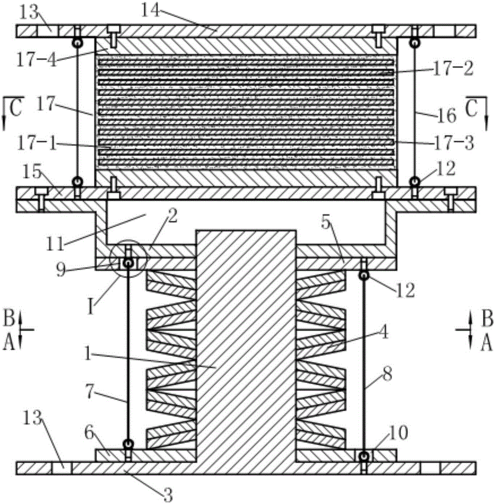
[0038] See figure 1 The three-dimensional seismic isolation device in this example is composed of a laminated rubber seismic isolation support and a vertical seismic isolation support connected in series.

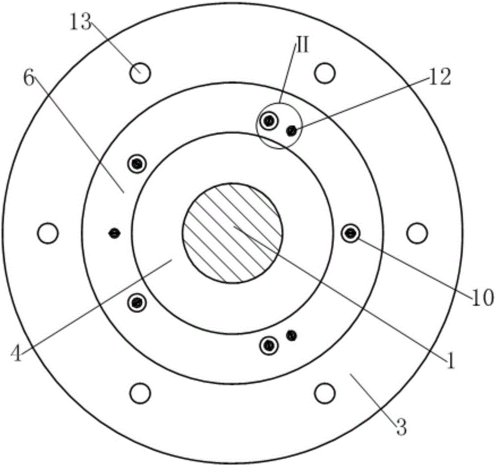
[0039] See figure 1 with Figure 4 , The laminated rubber shock isolation support includes an upper connecting plate 14, a lower connecting plate 15, a laminated rubber pad 17 clamped between the upper and lower connecting plates, and six tensile steel cables 16; wherein, the upper The connecting plate 14 and the lower connecting plate 15 are both disc-shaped, and the edge of the upper connecting plate 14 is provided with mounting holes 13; the main body of the laminated rubber pad 17 is made up of a layer of rubber 17-1 and a layer of steel plate 17-2 alternately After being laminated, it is formed by compression and vulcanization, and a rubber protective layer 17-3 is naturally formed around it during the compression and vulcanization process. The upper and lower end faces...

example 2

[0048] This example has the following differences from Example 1:

[0049] See Figure 7-9 The first group of pre-compressed steel cables 8 and the second group of pre-compressed steel cables 7 are both composed of three pre-compressed steel cables.

[0050] See Figure 7-9 , The lower end of the first group of pre-compressed steel cables 8 and the upper end of the second group of pre-compressed steel cables 7 are respectively fixed on the lower end plate 3 and the upper end with a steel cable self-locking anchor 18 instead of the eyebolt in Example 1. On board 2. The middle part of the lower end plate 3 is thickened and bulges upward to form an inverted washbasin shape to facilitate the installation of the steel cable self-locking anchor 18. In order to prevent dust and other debris from falling on the disc spring assembly 4 and affecting the normal operation of the damper, a rubber protective sleeve 19 is wrapped on the outside of the back pressure device. The two ends of the pr...

example 3

[0055] See Figure 13-15 The difference between this example and Example 2 is that the first group of pre-compressed steel cables 8 and the second group of pre-compressed steel cables 7 are both composed of five pre-compressed steel cables. The upper end of the guide rod 1 is fixedly connected to the middle part of the lower surface of the upper end plate 2 into one body, and the lower end extends downward along the central hole of the disc spring assembly 4 to the middle part of the upper bulge passing through the lower end plate 3; The lower end plate 3 is in dynamic fit with the outer surface of the guide rod 1. A movable space 11 for the lower end of the guide rod 1 to expand and contract is formed between the lower surface of the lower surface of the raised middle of the lower end plate 3 and the lower surface of the edge of the lower end plate 3.

[0056] Embodiments other than the above in this example are the same as in Example 2.


PUM


Abstract

The invention discloses a three-dimensional shock-insulation device capable of presetting vertical early stiffness. The three-dimensional shock-insulation device capable of presetting the vertical early stiffness includes a laminated rubber shock-insulation support and a vertical shock-insulation support, wherein the laminated rubber shock-insulation support and the vertical shock-insulation support are sequentially connected in series from top to bottom. The three-dimensional shock-insulation device capable of presetting the vertical early stiffness is characterized in that a back-pressing device is further arranged between two end plates of the vertical shock-insulation support and includes two sets of prepressing steel cables and two floating platens, wherein the number of each set of the prepressing steel cables is at least three, the two floating platens are respectively arranged on a guide rod between one end plate and a belleville spring set in a sleeving mode; the two sets of the prepressing steel cables are symmetrically distributed on the periphery of the belleville spring set around the axis of the guide rod in a linear state, one ends of each set of the prepressing steel cables are fixed to one corresponding floating platen, the other ends of each set of the prepressing steel cables penetrate through the other corresponding floating platen and are fixed to the end plate adjacent to the floating platen; and the two sets of the prepressing steel cables are tensioned so as to clamp the belleville spring set between the two floating platens all the time.

Description

Technical field [0001] The invention relates to a building anti-vibration (or vibration) device, in particular to a three-dimensional vibration isolation device in which a sandwich steel plate rubber pad and a vertical vibration isolation support are connected in series. Background technique [0002] The seismic isolation device is a seismic isolation device located between the building and the foundation. Early seismic isolation devices were mainly two-dimensional seismic isolation bearings (laminated rubber seismic isolation bearings) formed by alternately overlapping rubber and thin steel plates, which could only isolate the horizontal component of seismic waves. With the improvement of people's understanding of the multi-dimensional characteristics of earthquakes, three-dimensional seismic isolation devices have gradually received attention from researchers in this field. The most common three-dimensional seismic isolation device is composed of laminated rubber seismic isola...

Claims


Application Information

Patent Timeline
Patent Type & Authority Applications(China)
IPC IPC(8): E04H9/02E04B1/98E04B1/36
CPCE04H9/022
Inventor 沈珊胡济福胡济全
Owner ANHUI XINZE TECH CO LTD
Why Eureka
Try Eureka