Eureka AIR delivers breakthrough ideas for toughest innovation challenges, trusted by R&D personnel around the world.

Movable elevating device

A lifting device and lifting component technology, applied in the direction of lifting device, lifting frame, etc., can solve the problems of consuming a lot of time and labor, affecting production capacity and labor intensity, heavy parts and components, etc., achieving low manufacturing and maintenance costs, reducing electrical Automation components, highly automated effects

Inactive Publication Date: 2017-01-04
南宁钛银科技有限公司
View PDF5 Cites 7 Cited by
  • Summary
  • Abstract
  • Description
  • Claims
  • Application Information

AI Technical Summary

Problems solved by technology

Because of this, generally large-scale parts are relatively heavy. When moving large-scale materials due to work needs, multiple people are required to carry them, which not only wastes manpower, but also affects production progress.
The existing technology generally uses manual, forklift and hoisting for transportation. This transportation method has the following disadvantages: 1) High labor intensity and low efficiency: for manual transportation of materials, it takes a lot of time and labor, which not only increases labor intensity but also reduces production. Efficiency; 2) Moving is easy to be blocked: For forklifts to carry materials, due to the large size of forklifts, limited by the production site and equipment, it is often inconvenient to enter and exit, and the movement is easily blocked; for cranes to carry materials, because the hook and sling are located above the materials being carried , often hit the motor, workbench or cutterhead above the processing equipment, and the movement is easily blocked; 3) Unloading is inconvenient: For forklifts and cranes to carry materials, ropes are often used to fix the materials, and the ropes are used for hoisting and handling. It is difficult to take out the ropes during unloading, etc. In view of the above problems, someone has invented a multi-motor multi-screw structure and a scissor foot lifting structure. However, after long-term practice, the inventors have found that this type of mechanism has the disadvantages of complex structure and inconvenient operation. Therefore, for large-scale workpieces to be processed The mobile problem has become a key factor affecting production capacity and labor intensity, and the above defects have become difficult problems in this technical field

Method used


Image

  • Movable elevating device
  • Movable elevating device

Examples


Embodiment 1

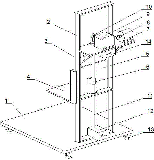
[0029] In the process of processing large-diameter gears such as sugarcane pressing or mining machinery, the inventor often consumes too much manpower and time due to the movement and clamping of large-scale gear blanks. Although the original mobile crane can quickly move and lift the gear blank, because the mechanical cutter head and motor and other mechanisms are installed above the workbench, when the mobile crane travels close to the workbench, its hook and wire often collide with the top parts of the equipment. There is no small hidden danger to the safety of the equipment.

[0030] In February 2016, the movable lifting device of the present invention was adopted, and according to its production requirements, the shape of the support plate 4 was appropriately improved, so that the support plate 4 and the processing table form butt teeth, which facilitates placing the gear on the work table. The working process of the device is as follows: move the lifting device to the fr...


PUM


Abstract

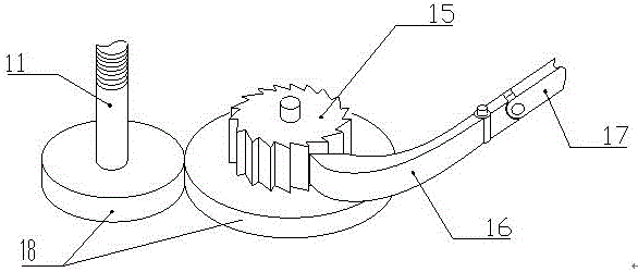
The invention belongs to the field of machine manufacturing, and particularly relates to a movable elevating device. The movable elevating device is characterized by comprising a support component, an elevating component, a moving component, a braking mechanism, a lead screw, a bevel gear, a driving component and a controller, wherein the supporting component comprises a base which is arranged in parallel to the ground and a support frame which is vertical to the base; the moving component which can be used for moving the elevating device is arranged at the bottom of the base; the elevating component is arranged on the support frame; a guide rail through which the elevating component can move up and down is arranged on longitudinal beams on the left and right sides of the support frame; an output shaft of the driving component is connected with the upper end of the lead screw through the bevel gear; the lower end of the lead screw is connected with the braking mechanism through a gear; the elevating component is electrically driven through the controller. The movable elevating device has the characteristics of high adaptability, low manufacturing and maintenance costs, safety, stability, high elevating speed, simple structure, high operability and the like.

Description

technical field [0001] The invention belongs to the field of mechanical manufacturing, in particular to a movable lifting device. Background technique [0002] With the continuous development of industry, the market's demand for processing large-scale materials is gradually increasing, and machining workshops are also processing more and more large-scale parts. Therefore, the handling problem in the process of large-scale material processing has become a key factor affecting production capacity and labor intensity. . Because of this, generally large-scale parts are relatively heavy. When moving large-scale materials due to work needs, multiple people are required to carry them, which not only wastes manpower, but also affects production progress. The existing technology generally uses manual, forklift and hoisting for transportation. This transportation method has the following disadvantages: 1) High labor intensity and low efficiency: for manual transportation of materials...

Claims


Application Information

Patent Timeline
Patent Type & Authority Applications(China)
IPC IPC(8): B66F7/06B66F7/28
CPCB66F7/0608B66F7/0625B66F7/28
Inventor 隆成柱隆小柱卢芝进
Owner 南宁钛银科技有限公司
Why Eureka
Eureka Blog
Learn More