
Embedded rolling device

An embedded, cloth-rolling technology, applied in the direction of winding strips, transportation and packaging, thin material handling, etc., can solve the problems of uneven cloth, uneven sides, not tight enough, etc. Tightening effect

Active Publication Date: 2017-01-04
浙江艾布特纺织科技有限公司
View PDF6 Cites 3 Cited by
  • Summary
  • Abstract
  • Description
  • Claims
  • Application Information

AI Technical Summary

Problems solved by technology

[0005] The purpose of the present invention is to overcome the disadvantages of the prior art, to overcome the problems of the existing cloth rolling device, the cloth needs a winding roller and the rolled out cloth is uneven, curled, uneven on both sides, and not tight enough, and provides Embedded rolling device

Method used


Image

  • Embedded rolling device
  • Embedded rolling device
  • Embedded rolling device

Examples


Embodiment

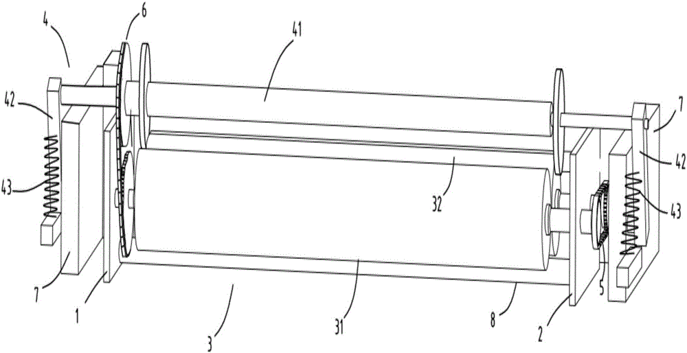
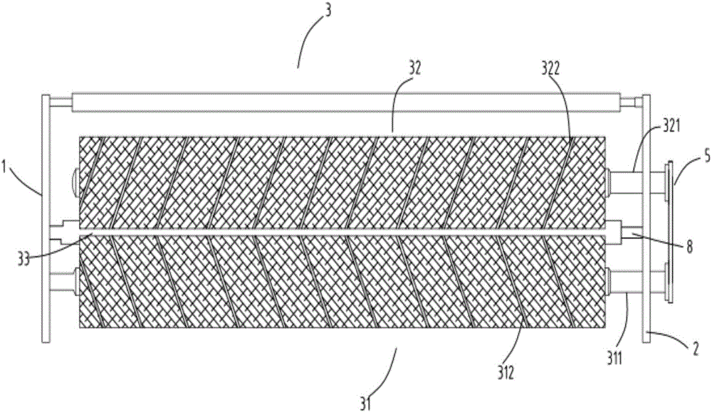
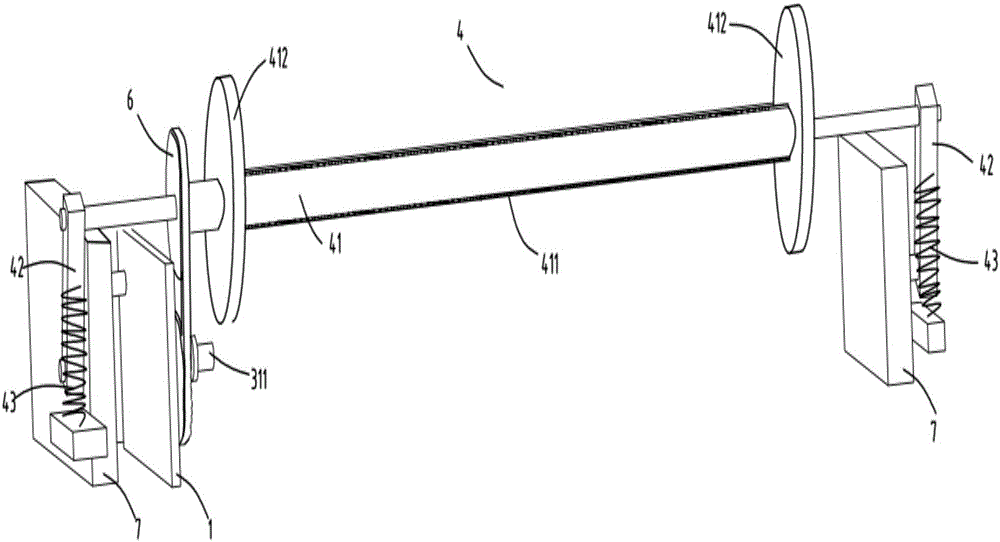
[0026] figure 1 is a schematic diagram of the embedded coiling device, figure 2 It is a schematic diagram of the structure of the cloth rolling device, image 3 It is a schematic diagram of the structure of the auxiliary winding device, Figure 4 It is a simplified schematic diagram of the rotation direction of each rotating part of the rolling device viewed from the right. Such as figure 1 , figure 2 , image 3 as well as Figure 4 As shown, what is provided in this embodiment is an embedded rolling device, including a left frame 1, a right frame 2, and a cloth rolling device 3; the cloth rolling device 3 includes a cloth rolling shaft a31 and a Cloth roll shaft b32, the speed of cloth roll shaft a31 is greater than that of cloth roll shaft b32; the cloth roll shaft a31 and cloth roll shaft b32 are arranged in parallel with a gap 33 between them; an auxiliary winding device 4 is also included; The auxiliary winding device 4 includes a roller 41, a fixed rod 42 and a ...


PUM


Abstract

The invention relates to an embedded rolling device which comprises a left machine frame, a right machine frame and a cloth rolling device. The cloth rolling device comprises a cloth rolling shaft a and a cloth rolling shaft b, and the cloth rolling shaft a and the cloth rolling shaft b rotate in the same direction. The rotation speed of the cloth rolling shaft a is larger than that of the cloth rolling shaft b. The cloth rolling shaft a and the cloth rolling shaft b are arranged in parallel, and a gap is reserved between the cloth rolling shaft a and the cloth rolling shaft b. The embedded rolling device further comprises an auxiliary winding device. The auxiliary winding device comprises a roller, fixing rods and springs. A cloth brush is arranged on the surface of the roller. The roller is driven by the cloth rolling shaft a to rotate, and the rotation direction of the roller is identical to that of the cloth rolling shaft a. Cloth penetrates through the gap and is rolled above the cloth rolling shaft a and the cloth rolling shaft b. The roller supports the cloth and assists in rolling. The problems that according to an existing cloth rolling device, a take-up roller is required by cloth rolling, rolled cloth is non-uniform and curly, the two sides of the cloth are not smooth, and the cloth is not tight enough are solved.

Description

technical field [0001] The invention relates to the technical field of textile equipment, in particular to an embedded rolling device. Background technique [0002] In the textile industry, the produced fabrics are generally coiled for storage or subsequent processing, and the curled fabric is more convenient for transportation. Most of the fabric rolling devices simply use the rotation around the shaft to roll the fabric. During the cloth rolling process, the cloth is unevenly rolled and the curls on both sides are uneven. [0003] Citing a Chinese invention patent with the application number 201310605512.6 published on March 5, 2014, an improved fabric rolling machine is disclosed, which uses the rolling device and the width adjustment devices arranged at both ends to ensure that the gap between the two width adjustment devices The distance of the cloth is consistent with the distance of the cloth, which ensures that the cloth will not shift during the rolling process, en...

Claims


Application Information

Patent Timeline
Patent Type & Authority Applications(China)
IPC IPC(8): B65H18/20B65H23/34B65H23/032
CPCB65H18/20B65H23/0324B65H23/34B65H2701/1133B65H2701/174
Inventor 丁震华
Owner 浙江艾布特纺织科技有限公司
Learn More