
Round wire rod label sticking jig and application method thereof

A label sticking and wire technology, which is applied in the field of circular wire label sticking fixtures, can solve the problems of low bonding efficiency, prone to errors, and difficult operation, so as to improve the bonding quality, avoid sticking deviation, and reduce production. cost effect

Inactive Publication Date: 2017-01-04
GEER TECH CO LTD
View PDF6 Cites 12 Cited by
  • Summary
  • Abstract
  • Description
  • Claims
  • Application Information

AI Technical Summary

Problems solved by technology

Most of the current circular wire labels are pasted by hand, and the position of the label is often incorrect, resulting in the occurrence of the problem of label pasting deviation; secondly, due to the limitations of manual operations and skilled procedures, there will be problems during the label pasting process. Severe bulging, air bubbles and warping, etc., are prone to label peeling during product use; in addition, purely manual operation, slow operation speed, reduces the efficiency of label pasting, and is prone to mistakes, increasing production costs
[0003] Especially for pasting labels on round wires, since most round wires are thin, the middle of the label needs to be glued to the round wire, and the two ends of the label are opposite and bonded to each other. The quality requirements are high, the operation is difficult, and the bonding efficiency is high. lower

Method used


Image

  • Round wire rod label sticking jig and application method thereof
  • Round wire rod label sticking jig and application method thereof
  • Round wire rod label sticking jig and application method thereof

Examples


Embodiment Construction

[0040] In order to make the purpose, technical solutions and advantages of the embodiments of the present invention more clear, the technical solutions in the embodiments of the present invention will be clearly and completely described below in conjunction with the drawings in the embodiments of the present invention.

[0041] In the description of the present invention, it should be noted that the orientations or positional relationships indicated by the terms "front", "rear", "upper", "lower", "left", "right" etc. are based on the The positional relationship is only for the convenience of describing the present invention and simplifying the description, but does not indicate or imply that the referred device or element must have a specific orientation, be constructed and operated in a specific orientation 30, and thus should not be construed as a limitation of the present invention. In addition, the terms "first" and "second" are used for descriptive purposes only, and shoul...


PUM


Abstract

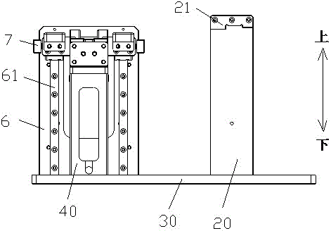
The invention provides a round wire rod label sticking jig and an application method thereof. The round wire rod label sticking jig comprises a positioning assembly and a sticking assembly; the positioning assembly is used for positioning a label and comprises two positioning seats which are mutually symmetric; a gap through which a round wire rod passes is formed between the two positioning seats; the sticking assembly is arranged below the positioning assembly and comprises two pressing wheels which are arranged adjacently and are used for tightly pressing and sticking the label. By setting the positioning assembly for positioning the label, the label is accurately positioned, and problems of deviated label sticking and the like are avoided; after the label is put onto the two positioning seats, the gap is just located in the middle of the label and the round wire rod passes through the gap, so that the middle part of the label is stuck on the round wire rod; the label is extruded from the middle, so that the label is firmly stick, quality defects including bumps, bubbles, warping and the like are not caused and the sticking quality of the label is improved; furthermore, the sticking efficiency is also greatly improved and the production cost is reduced.

Description

technical field [0001] The invention belongs to the technical field of tooling equipment, and in particular relates to a circular wire label sticking jig and a method for using the circular wire label sticking jig. Background technique [0002] As an assembly process in the manufacturing industry, label pasting is widely used in the electronics and electrical appliance manufacturing industries. Most of the current circular wire labels are pasted by hand, and the position of the label is often incorrect, resulting in the occurrence of the problem of label pasting deviation; secondly, due to the limitations of manual operations and skilled procedures, there will be problems during the label pasting process. Severe bulging, air bubbles and warping, etc., are prone to label peeling during product use; in addition, purely manual operation, slow operation speed, reduces the efficiency of label pasting, and is prone to errors, increasing production costs. [0003] Especially for p...

Claims


Application Information

Patent Timeline
IPC IPC(8): B65C3/02B65C9/36B65C9/08
CPCB65C3/02B65C9/08B65C9/36B65C2009/0018
Inventor 张敏李晓峰
Owner GEER TECH CO LTD
Learn More