
Encapsulation method for integral molding of stringer panel structure

A technology of integral molding and packaging method, which is applied in the field of resin matrix composite material molding, and can solve the problems of inability to realize packaging and cavity packaging.

Active Publication Date: 2017-01-04
AVIC COMPOSITES
View PDF6 Cites 4 Cited by
  • Summary
  • Abstract
  • Description
  • Claims
  • Application Information

AI Technical Summary

Problems solved by technology

However, the encapsulation of the integral wall panel with closed structure after assembling the mold cannot be realized by traditional methods.
For example, if there are 4 "J"-shaped cross-section long stringers with composite material integral wall panels, considering the requirements of the upper flange profile and positioning of the parts, two adjacent stringers share one upper flange shape mold, and the upper flange shape mold is assembled. After the flange shape molding, the cavity between the two stringers cannot be packaged

Method used


Image

  • Encapsulation method for integral molding of stringer panel structure
  • Encapsulation method for integral molding of stringer panel structure
  • Encapsulation method for integral molding of stringer panel structure

Examples


Embodiment 1

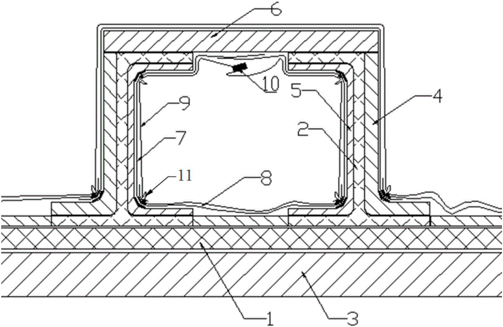
[0036] by figure 1 The wall plate with two "J"-shaped cross-section long stringers is shown as an example. In order to ensure the surface accuracy of the upper flange of the long stringer, the outer surface of the upper flange of the stringer adopts a rigid upper flange shape mold, and the two long stringers The girders share one upper flange shape mold, and after assembling the upper flange shape mold, a closed cavity is formed between the girders. This structure cannot be packaged after the upper flange shape mold is assembled.

[0037] In order to solve the problem of forming and encapsulating such integral wall panels, this technical solution is adopted. Before assembling the shape mold of the upper flange of the girders, pre-position the auxiliary materials and the vacuum film in the corner area of ​​the cavity between the girders where the bridge is easy to be bridged so that they can be attached to the mold, so as to solve the problem that the upper flange shape mold of...

Embodiment 2

[0049] image 3 The integral wall plate with 4 long stringers shown in the figure, in order to ensure the surface accuracy of the upper flange of the stringer, the outer surface of the upper flange of the stringer adopts a rigid upper flange shape mold, and every two stringers share one upper flange The specific method of encapsulating the structure of the edge shape mold is as follows:

[0050] (a) Prepare the side auxiliary material 7 on the inside of the stringer cavity, the auxiliary material 8 on the inside bottom according to the distance between the lower corners of the mold 5 on the inside of the stringer, and the width of one side is 5-20 mm, and the width direction of the auxiliary material 7 on the side is according to the mold on the inside of the stringer 5 Follow the shape, the lower side is 5-20mm wider than the lower corner of the inner mold 5 of the truss, and the other side is required to be lapped at the upper part, and the lap width is at least 10mm.

[00...


PUM


Abstract

The invention belongs to a resin-based composite material molding technology, and relates to an encapsulation method for integral molding of a stringer panel structure. For the stinger panel structure which cannot be encapsulated without being opened after stringer molds are assembled, before a stringer upper flange shape mold is assembled, an auxiliary material and a vacuum film which are arranged between stringers are positioned between the stringers in advance to be attached to the mold, and after the edges of the two sides of the vacuum film are sealed, the two ends are reserved to be sealed with the outer side vacuum film, namely, the panel shape mold after the mold assembling is completed; the problem that after the upper flange shape mold is assembled, a non-opening area of a cavity between the stringers cannot be encapsulated is solved, and the auxiliary material and vacuum film bridging phenomenon caused by the fact that vacuumizing cannot be operated after encapsulation is avoided.

Description

technical field [0001] The invention belongs to the molding technology of resin-based composite materials, and relates to an encapsulation method for the integral molding of a long stringer wall plate structure. Background technique [0002] Compression during composite molding is an important aspect to ensure the quality of composite components. At present, the vacuum bag method is widely used in the molding of high-performance composite materials in most aerospace fields, and vacuum film packaging is a key link in the vacuum bag molding method of high-performance composite materials. Integral siding with stringers is a widely used structural form in the design of composite structures, and is basically formed by vacuum bagging. The usual integral wall panel is to encapsulate the vacuum film after the mold assembly such as the stringer is completed. However, the traditional method cannot be used for the encapsulation of the integral wall panel whose structure is not open a...

Claims


Application Information

Patent Timeline
IPC IPC(8): B29C70/44B29C70/46
CPCB29C70/443B29C70/446B29C70/462
Inventor 高艳秋王海雷
Owner AVIC COMPOSITES
Learn More