
Intelligent transmission laser cutting machine

A laser cutting machine, intelligent technology, applied in the direction of laser welding equipment, welding equipment, metal processing equipment, etc., can solve the problem that the laser cutting machine cannot automatically feed, adjust and control the position of materials, etc., to achieve easy promotion, improve overall performance, and structure Simple and reasonable effect

Inactive Publication Date: 2017-01-04
WENZHOU QIHAO LASER TECH
View PDF4 Cites 0 Cited by
  • Summary
  • Abstract
  • Description
  • Claims
  • Application Information

AI Technical Summary

Problems solved by technology

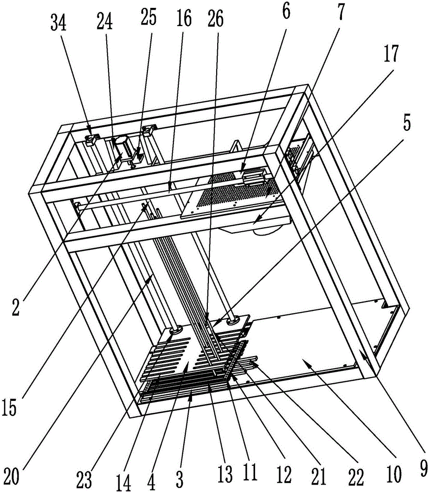
[0004] In order to overcome the shortcomings of the background technology, the present invention provides an intelligent transmission laser cutting machine, which mainly solves the problem that the existing laser cutting machine cannot automatically feed and adjust and control the position of the material during the feeding process. The intelligent transmission laser cutting machine The structure is simple and reasonable. The controller controls the lifting motor to adjust the height of the lifting platform, so that the material conveying device transmits the material to the working platform for laser cutting. Adjust the position of several adjusting rollers to fix the irregularly shaped materials on the lifting platform, avoiding the impact of the material position on the laser cutting process, greatly improving the overall performance of the intelligent transmission laser cutting machine, reducing the labor intensity of personnel, and cutting materials Beautiful and generous, practical and simple, high reliability, easy to promote

Method used


Image

  • Intelligent transmission laser cutting machine
  • Intelligent transmission laser cutting machine
  • Intelligent transmission laser cutting machine

Examples


Embodiment Construction

[0015] Embodiments of the present invention will be further described below in conjunction with accompanying drawings:

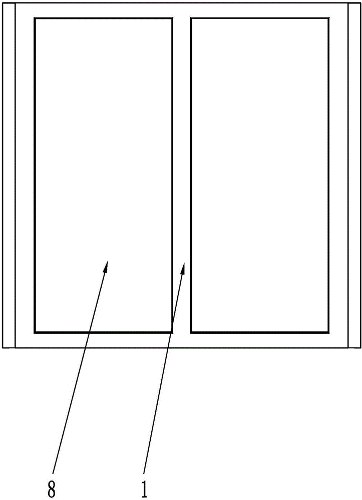
[0016] like Figure 1 to Figure 7 As shown, an intelligent transmission laser cutting machine includes a sheet metal cover 1, a material lifting motor 2, a groove plate 3, a material lifting platform 4, an adjustment roller 5, a material transmission device 6 and a working platform 7, and the sheet metal The outer cover 1 is provided with two left and right symmetrical outer cover doors 8 and a controller. The sheet metal outer cover 1 is provided with a fixed bracket 9 and a bottom plate 10 fixedly connected by bolts. Grooved plate 3, bead 11 is provided with installation hole 12, and grooved plate 3 is provided with evenly distributed groove structure 13, and the top of grooved plate 3 is provided with the lifting platform 4 that cooperates with grooved plate 3, lifts The adjustment gap 14 corresponding to the groove structure 13 is arranged on the materi...


PUM


Abstract

The invention relates to an intelligent transmission laser cutting machine, and mainly solves the problem that an existing laser cutting machine cannot automatically feed a material or adjust and control a material position in a material feeding process. The intelligent transmission laser cutting machine comprises a metal plate housing, a material lifting motor, a groove plate, a material lifting platform, adjusting rollers, a material conveyer and a working platform; the groove plate fixedly connected with a bottom plate through a batten is arranged on the bottom plate; evenly distributed groove structures are arranged on the groove plate; the material lifting platform is arranged above the groove plate; adjusting gaps corresponding to the groove structures correspondingly are arranged on the material lifting platform; the adjusting rollers are arranged at the groove structures and the adjusting gaps; the material lifting motor is arranged above the material lifting platform; the material conveyer, a laser head and the working platform are arranged at the upper right end of a fixed support. The intelligent transmission laser cutting machine is reasonable and simple in structure, reduces the labor intensity of a worker, is high in efficiency, practical, convenient, high in operational reliability, and easy to popularize, and realizes attractive cutting.

Description

technical field [0001] The invention relates to the technical field of laser cutting, in particular to an intelligent transmission laser cutting machine. Background technique [0002] Laser cutting is to focus the laser emitted from the laser into a high power density laser beam through the optical path system. The laser beam irradiates the surface of the workpiece to make the workpiece reach the melting point or boiling point, and at the same time, the high-pressure gas coaxial with the beam blows away the molten or gasified debris. With the movement of the relative position of the beam and the workpiece, the material will eventually form a slit, so as to achieve the purpose of cutting. Laser cutting process replaces the traditional mechanical knife with an invisible beam. It has the characteristics of high precision, fast cutting, not limited to cutting patterns, automatic typesetting saves materials, smooth incision, and low processing cost. It will gradually improve or ...

Claims


Application Information

Patent Timeline
Patent Type & Authority Applications(China)
IPC IPC(8): B23K26/38B23K26/08B23K26/70
CPCB23K26/08B23K26/38B23K26/702
Inventor 周蕴
Owner WENZHOU QIHAO LASER TECH
Learn More