Split-type lateral backup roll swing arm structure for eighteen-high mill
A side support roll and side support technology, which is applied in metal rolling, metal rolling, metal processing equipment and other directions, can solve problems such as affecting production efficiency and cost, and increasing the operation and maintenance workload of side support rolls and intermediate rolls. Achieve the effect of improving production efficiency, simplifying the structure of intermediate rolls, and convenient roll changing operations
- Summary
- Abstract
- Description
- Claims
- Application Information
AI Technical Summary
Problems solved by technology
Method used
Image

Examples
Embodiment 1
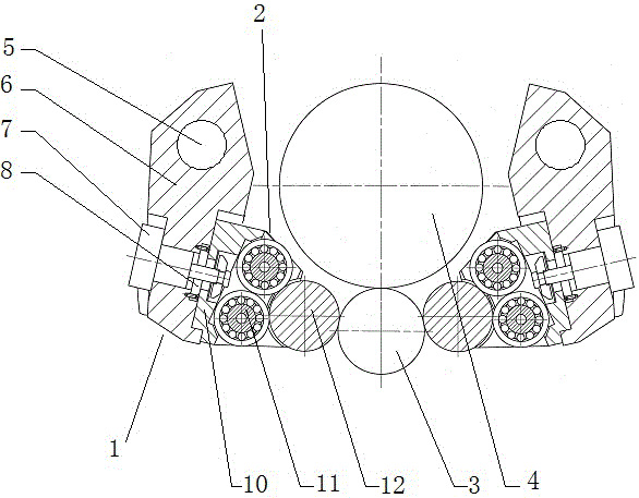
[0023] In order to overcome the problem that the side support rolls and the swing arm and the middle roll of the existing 18-high rolling mill are set accessories, resulting in a substantial increase in the operation and maintenance workload of the side support rolls and the middle roll, thereby affecting the production efficiency and cost, this embodiment provides a figure 1 The split-type side support roll swing arm structure of the eighteen-high rolling mill shown includes a swing arm assembly 1 and a side support roll assembly 2, and the swing arm assembly 1 and the side support roll assembly 2 are connected and fixed by a clamping cylinder 7 .
[0024] Such as figure 1 As shown, the work roll 3 and the intermediate roll 4 are installed on the frame of the rolling mill, and the swing arm assembly 1 and the side support roll assembly 2 are installed on the side of the work roll 3 and the intermediate roll 4, which is different from the side support of the conventional eight...
Embodiment 2
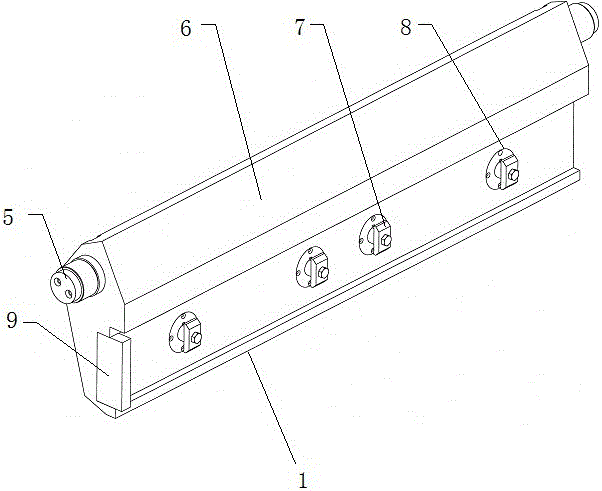
[0027] On the basis of Example 1, such as figure 2 As shown, the swing arm assembly 1 includes a swing arm body 6, the upper end of the swing arm body 6 is a swing arm hinge hole 5, and the lower end is provided with a plurality of installation holes along the long side direction, and the cylinder head 13 of the clamping cylinder 7 passes through The mounting hole is connected to the side support roller assembly 2, and a guide plate 8 is arranged between the cylinder head 13 and the mounting hole. A positioning baffle 9 is installed at the end of the swing arm body 6 , and the positioning baffle 9 protrudes from the end surface of the swing arm body 6 end.
[0028] The hinged hole 5 of the swing arm is not associated with the intermediate roll 4, and is directly fixed on the rolling mill, that is, the whole set of side support roll swing arm structure and the assembly of the intermediate roll are two sets of independent parts. The side support roller assembly 2 and the swing...
Embodiment 3
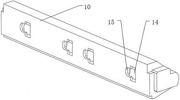
[0031] On the basis of Example 2, such as image 3 As shown, the shape of the cylinder head 13 of the clamping cylinder 7 is a T-shaped cylinder head. Such as Figure 4 and Figure 5 As shown, the side support roll assembly 2 is composed of a side roll support 10 and a side support roll 12, the side support roll 12 is installed on the side roll support 10, and the side roll support 10 is provided with a plurality of rectangular holes 14 The T-shaped combination hole combined with the half-waist hole 15 has a counterbore 16 corresponding to the T-shaped cylinder head shape of the clamping cylinder 7 at the corresponding position inside the half-waist hole 15, and the clamping cylinder 7 retracts the clamp When tight, the T-type cylinder head is pressed in the counterbore 16.
[0032] Such as image 3 and Figure 4 As shown, when the clamping cylinder 7 is retracted and clamped, the T-shaped cylinder head of the clamping cylinder is pressed into the counterbore 16 correspon...
PUM
 Abstract
Description
Claims
Application Information
 - Generate Ideas
- Intellectual Property
- Life Sciences
- Materials
- Tech Scout
- Unparalleled Data Quality
- Higher Quality Content
- 60% Fewer Hallucinations
Browse by: Latest US Patents, China's latest patents, Technical Efficacy Thesaurus, Application Domain, Technology Topic, Popular Technical Reports.
© 2025 PatSnap. All rights reserved.Legal|Privacy policy|Modern Slavery Act Transparency Statement|Sitemap|About US| Contact US: help@patsnap.com