
Controllable composite damping structure adopting magnetostrictive material

A magnetostrictive material and composite damping technology, applied in the direction of vibrating fluids, electromechanical devices, electrical components, etc., can solve the problems of large control circuit volume, poor energy conversion characteristics, high impedance, etc., and achieve small volume, volume change The effect of small and large control range

Inactive Publication Date: 2017-01-04
NANJING UNIV OF SCI & TECH
View PDF6 Cites 3 Cited by
  • Summary
  • Abstract
  • Description
  • Claims
  • Application Information

AI Technical Summary

Problems solved by technology

However, when piezoelectric materials are used in damping and vibration reduction structures, there are still some disadvantages: piezoelectric materials have capacitive characteristics, and the output of converting mechanical energy into electrical energy has the characteristics of high impedance, high voltage and low current, and the external control circuit needs The large-volume matching inductor leads to a large volume of the control circuit of the damping structure; when the piezoelectric material is used in the damping structure, the d31 working mode is usually used, that is, the polarization direction is perpendicular to the direction of the external force, and its electromechanical coupling coefficient Only about 0.3, the energy conversion characteristics are poor, resulting in a small adjustable range of damping

Method used


Image

  • Controllable composite damping structure adopting magnetostrictive material
  • Controllable composite damping structure adopting magnetostrictive material
  • Controllable composite damping structure adopting magnetostrictive material

Examples


Embodiment 1

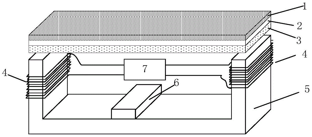
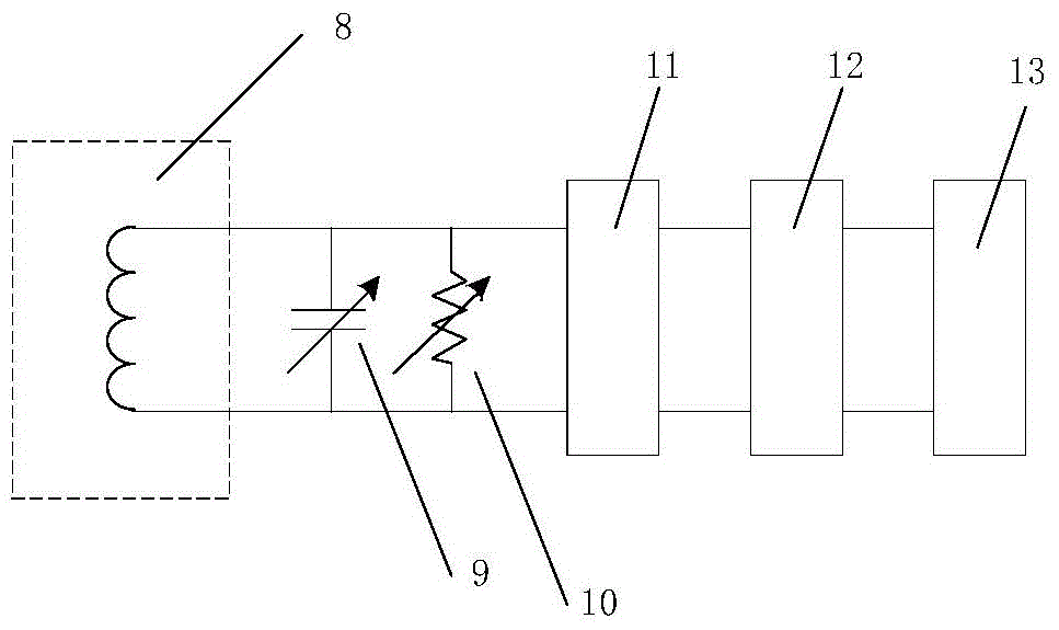
[0026] to combine figure 1 , this embodiment includes: a viscoelastic material layer 1, a magnetostrictive material layer 2, an elastic substrate 3, an electromagnetic induction coil 4, a magnetic conductor 5, a permanent magnet 6 and a matching control circuit 7; the viscoelastic material layer 1 is compounded in The magnetostrictive material layer 2 provides initial damping for the composite damping structure; the magnetostrictive material layer 2 is compounded on the elastic substrate 3 for coupling the mechanical deformation of the elastic substrate 3, and based on its inverse magnetostrictive effect, the The mechanical energy generated by the mechanical deformation of the elastic base layer 3 is converted into magnetic energy, thereby generating dynamic magnetization; the electromagnetic induction coil 4 is used to convert the dynamic magnetization into electrical energy and output an electrical signal, and then realize damping control under the action of the matching cont...

Embodiment 2

[0030] to combine image 3 , the composite damping structure shown in this embodiment is basically the same as that of Embodiment 1, the difference is that this embodiment does not use a magnetic conductor, but the electromagnetic induction coil 4 is directly wound on the viscoelastic material layer 1, the magnetic induction coil The composite body formed by the elastic material layer 2 and the elastic substrate 3 realizes electromagnetic induction and converts magnetic energy into electrical energy. At the same time, by arranging the permanent magnet 6 at one end of the magnetostrictive material, the application of the bias magnetic field can be realized without providing a magnetizer.

[0031]In fact, in the present invention, the permanent magnet 6 can be flexibly arranged in different positions according to the use environment, as long as a bias magnetic field can be applied to the magnetostrictive material layer 2, so that the magnetostrictive material 2 works at the maxi...


PUM


Abstract

The invention provides a controllable composite damping structure adopting a magnetostrictive material. The controllable composite damping structure comprises a magnetostrictive material layer and a viscoelastic material layer which are attached to an elastic substrate, an electromagnetic induction coil and a matching control circuit; the elastic substrate can be a controlled object and can also be a structural part which is additionally arranged and used for being connected with the controlled object; the magnetostrictive material layer is used for coupling mechanical deformation of the elastic substrate and converting mechanical energy generated during mechanical deformation of the elastic substrate into magnetic energy based on the counter-magnetostrictive effect, and consequently dynamic magnetization is generated; the viscoelastic material layer provides initial damping for the composite damping structure; the electromagnetic induction coil converts the magnetic energy generated by the magnetostrictive material layer into electric energy and then outputs the electric energy to the matching control circuit; the matching control circuit is used for controlling the magnitude of the damping of the composite damping structure. Damping parameters of the controllable composite damping structure can be controlled, the control range is wide, and the control circuit for controlling damping is small in size.

Description

technical field [0001] The invention relates to an adjustable damping damping structure, in particular to an adjustable composite damping structure using magnetostrictive materials. Background technique [0002] The traditional composite damping structure is composed of rubber and other viscoelastic polymer materials and constrained layers on the controlled object. The performance parameters such as stiffness and damping of this composite damping structure cannot be adjusted during use. The traditional composite damping structure is a passive damping structure, and generally the damping cannot be adjusted, so it is difficult to adapt to the complex and changeable dynamic environment. [0003] With the development of piezoelectric materials, the performance of the damping structure becomes adjustable. When the piezoelectric material is used for vibration reduction of the damping structure, the external branch circuit as the control system is connected in parallel with the pi...

Claims


Application Information

Patent Timeline
IPC IPC(8): B06B1/06H02K35/06
Inventor 卞雷祥朱炜芮筱亭杨富锋王国平于海龙
Owner NANJING UNIV OF SCI & TECH
Learn More