Bird driving device for high-voltage power transmission tower

A transmission tower and bird repelling technology, which is applied in the installation of cables, electrical components, overhead installation, etc., can solve the problems of ineffective bird repelling, bird scaring and driving, simple structure of bird repelling device, etc., and achieve the effect of bird repelling Obvious, expand the range, enhance the effect of bird repelling effect

Inactive Publication Date: 2017-01-04
金英花
View PDF5 Cites 5 Cited by
  • Summary
  • Abstract
  • Description
  • Claims
  • Application Information

AI Technical Summary

Problems solved by technology

[0003] However, the existing bird repellents used on high-voltage transmission towers have a simple structure, and the effect of repelling birds is not obvious. As a result, most of the simple bird repelling devices use light reflection to drive birds away. This method is too simple and can only scare and drive some birds away.

Method used


Image

  • Bird driving device for high-voltage power transmission tower
  • Bird driving device for high-voltage power transmission tower
  • Bird driving device for high-voltage power transmission tower

Examples


no. 1 example

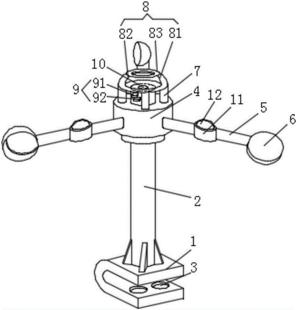
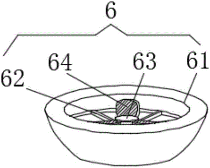
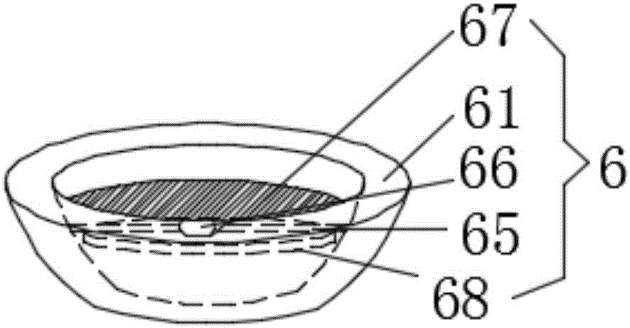
[0019] see figure 1 , figure 2 and Figure 4 , This patent provides the first embodiment: a high-voltage transmission tower bird repelling device, including a U-shaped base 1, a support rod 2 is vertically installed on the U-shaped base 1, and a mounting hole is provided in the middle of the U-shaped base 1 3. A rotating shaft 4 is installed on the top of the support rod 2, and a plurality of rotating arms 5 are fixedly installed on the side wall of the rotating shaft 4. The middle part of the rotating arm 5 is provided with an auxiliary wind bowl 11, and the auxiliary wind bowl 11 An auxiliary mirror 12 is rotatably installed in the inner cavity, and the head end of the rotating arm 5 is provided with a wind bowl 6. The number of the rotating arm 5 is at least three, and the rotating arm 5 takes the support rod 2 as the center of rotation. Symmetrically distributed, the rotating shaft 4 is fixedly installed with a reflection device 8 through the support feet 7 evenly insta...

no. 2 example

[0022] see figure 1 , image 3 and Figure 4 , this patent provides a second embodiment: a high-voltage transmission tower bird repelling device, including a U-shaped base 1, a support rod 2 is vertically installed on the U-shaped base 1, and a mounting hole is provided in the middle of the U-shaped base 1 3. A rotating shaft 4 is installed on the top of the support rod 2, and a plurality of rotating arms 5 are fixedly installed on the side wall of the rotating shaft 4. The middle part of the rotating arm 5 is provided with an auxiliary wind bowl 11, and the auxiliary wind bowl 11 An auxiliary mirror 12 is rotatably installed in the inner cavity, and the head end of the rotating arm 5 is provided with a wind bowl 6. The number of the rotating arm 5 is at least three, and the rotating arm 5 takes the support rod 2 as the center of rotation. Symmetrically distributed, the rotating shaft 4 is fixedly installed with a reflection device 8 through the support feet 7 evenly install...


PUM


Abstract

The invention discloses a bird driving device for a high-voltage power transmission tower. The bird driving device comprises a U-shaped base, a support rod is vertically installed on the U-shaped base, an installation hole is formed in the middle of the U-shaped base, and a rotating shaft is rotatably installed on the top of the support rod; multiple rotating arms are fixedly installed on the side wall of the rotating shaft, the head end of each rotating arm is provided with a wind bowl, the middle of each rotating arm is provided with an auxiliary wind bowl, and an auxiliary mirror is rotatably installed in an inner cavity of each auxiliary wind bowl. By driving birds through a sound-light transmitter, bird driving can be conducted through both sound waves and light waves, and the bird driving effect is more obvious; by cooperatively using a reflection device and the auxiliary wind bowls, the bird driving range can be widened by changing irradiation paths of the sound waves and the light waves in the rotating process of the rotating shaft; by installing rotatable mirror vanes in the wind bowls, the irradiation frequency of light in the bird driving area can be increased in the rotating process of the mirror vanes, and then the bird driving effect is enhanced.

Description

technical field [0001] The invention relates to the technical field of bird-repelling devices for high-voltage equipment, in particular to a high-voltage transmission tower bird-repelling device. Background technique [0002] In a broad sense, all means to prevent harmful birds from invading their own territories, such as farms, orchards, wind power plants, and military and civilian airports, and thus endangering their labor results or equipment safety are called bird repelling; in a narrow sense, bird repelling refers specifically to military and civilian use. In order to protect the safety of aircraft take-off and landing, the airport prevents birds from being sucked into the aircraft engine when the aircraft takes off and lands at high speed, or hits the aircraft body, landing gear, tail, windshield, etc. All measures taken on the landing runway or taxiway to prevent bird invasion, such as auditory threats, visual deterrents, direct hunting, chemical, ecological or radar ...

Claims


Application Information

Patent Timeline
IPC IPC(8): A01M29/08A01M29/10A01M29/16H02G7/00
CPCA01M29/08A01M29/10A01M29/16H02G7/00
Inventor 金英花
Owner 金英花
Why Eureka
Try Eureka