
Hole type transplanting machine

A technology of transplanting machine and frame, which is applied in the field of agricultural transplanting, can solve the problems that the angle cannot be adjusted, and achieve the effects of reducing the cost of transplanting, good quality, and simple angle adjustment

Active Publication Date: 2017-01-04
QINGDAO AGRI UNIV
View PDF8 Cites 5 Cited by
  • Summary
  • Abstract
  • Description
  • Claims
  • Application Information

AI Technical Summary

Problems solved by technology

However, the existing transplanting machines cannot achieve adjustable angles, so it is urgent to break the traditional technology and seek an efficient and high-quality transplanting device

Method used


Image

  • Hole type transplanting machine
  • Hole type transplanting machine
  • Hole type transplanting machine

Examples


Embodiment 1

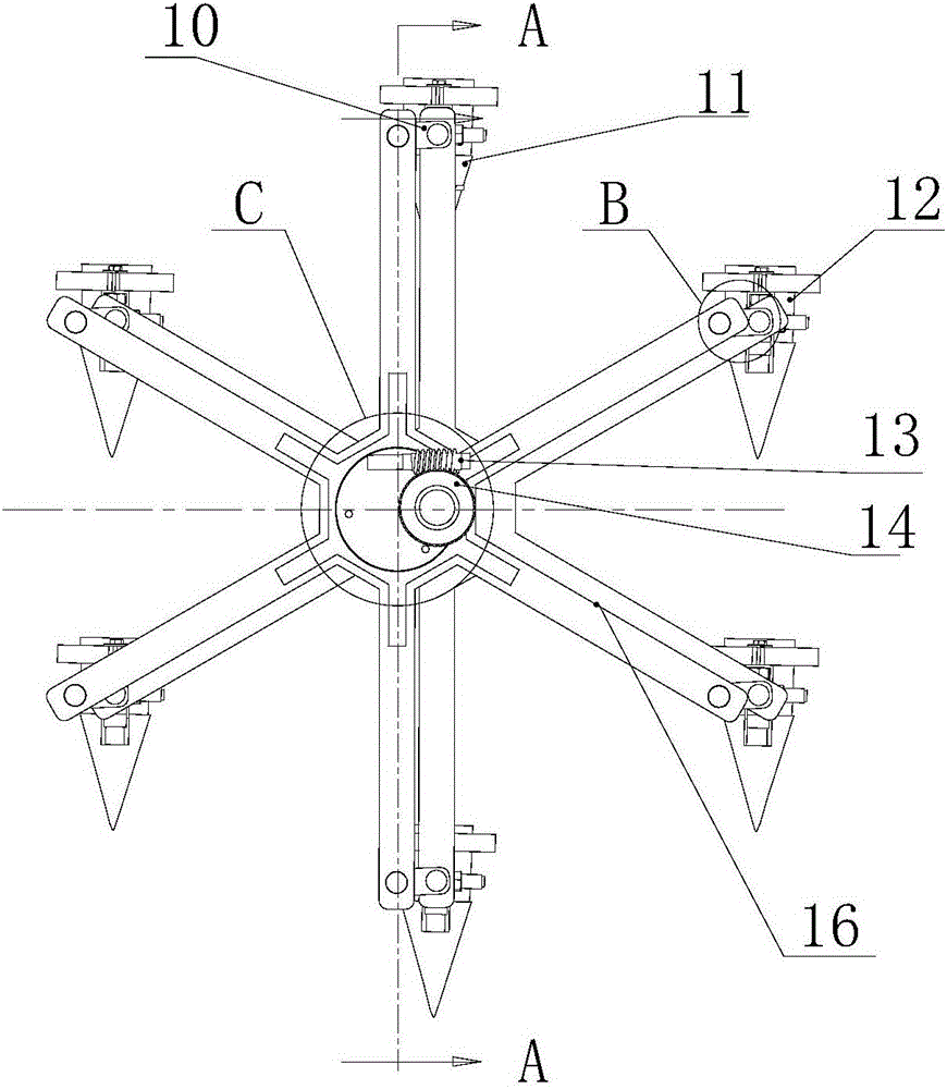
[0035] Hole type transplanting machine of the present invention such as figure 1 As mentioned above, the hole-type transplanting machine is driven by ground wheels and operated in two rows. Including frame 2, angle adjustment transplanting part, power transmission part, projecting seedling part and covering soil suppressing part, the angle adjusting transplanting part, power transmission part, projecting seedling part and covering soil suppressing part are all arranged on the frame 2. The front end of the frame 2 is provided with a traction frame 1, and the tractor positioned at the front of the transplanter is connected with the traction frame 1. When the tractor moves, it pulls the traction frame 1 to move forward, and the traction frame 1 drives the transplanter to move through the power transmission unit.

[0036] The power transmission part includes a ground wheel 7, four groups of sprockets and two groups of upper and lower bevel gears, the four groups of sprockets are a...

Embodiment 2

[0048] The difference from Example 1 is: in order to solve the problem of carrying soil when the transplanter leaves the soil, and reduce the disturbance of the transplanter to the soil, the connection between the transplanter 4 and the centering transplanting wheel is provided with a hydraulic cylinder 23. The cylinder body of the hydraulic cylinder 23 is fixed on the centering transplanting wheel, and one end of the transplanting frame connecting shaft 406 is connected with the piston rod of the hydraulic cylinder 23 while being connected with the centering transplanting wheel. The heart transplanting wheel is provided with a slideway 22, and the end of the transplanting frame connecting shaft 406 can slide up and down along the slideway 22. Its working principle is to utilize the hydraulic cylinder to take the lower part 405 of the transplanting device out of the transplanting hole quickly. Such as Figure 11 As shown, when the transplanter rotates to the state at the lowe...


PUM


Abstract

The invention relates to the field of agricultural transplanting, in particular to a hole type transplanting machine. The hole type transplanting machine comprises a parallelogram device, wherein the parallelogram device comprises eccentric transplanting wheels, aligned transplanting wheels and baffles, wherein the eccentric transplanting wheels are positioned at the inner sides of the corresponding aligned transplanting wheels; the eccentric transplanting wheels are connected with the aligned transplanting wheels by driving shafts; centers of the aligned transplanting wheels are fixed on the corresponding driving shafts; the driving shafts are rotationally connected with a rack; the eccentric transplanting wheels are eccentrically arranged on the driving shafts, and are connected with the top ends of the corresponding aligned transplanting wheels by short rods; the baffles are fixed at the outer sides of the middles of the eccentric transplanting wheels; the centers of the baffles are superposed with those of the eccentric transplanting wheels; a sleeve is eccentrically fixed on the surface of the outer side of each baffle; each sleeve is fixedly sleeved with a worm gear; each driving shaft penetrates through the corresponding sleeve and is connected with the corresponding aligned transplanting wheel; a clearance is reserved between the outer surface of each driving shaft and the inner surface of the corresponding sleeve; a plurality of rollers are symmetrically arranged on the inner side surfaces of the baffles relative to the centers of the baffles. According to the hole type transplanting machine, inclined inserting of crop seedlings is guaranteed, and the transplanting effect and transplanting quality of crops are improved; the hole type transplanting machine is simple and reliable in angle adjustment, easy to operate and high in angle adjusting precision.

Description

technical field [0001] The invention relates to the field of agricultural transplanting, in particular to a hole-type transplanting machine. Background technique [0002] Mechanical transplanting technology is widely used in transplanting economic crops such as tobacco, or in agricultural crops such as sweet potatoes, vegetables, and cotton. Adopting seedling raising and transplanting technology can increase the yield per mu of crops, greatly shorten the growth period of crops, and can also improve the ability of crops to resist insects, drought, salt and alkali, and cold damage. The existing manual transplanting is cumbersome and complicated, the row and plant spacing of transplanting cannot be effectively guaranteed, the planting depth is different, the quality after transplanting, the later survival rate and the yield are also greatly reduced, resulting in the production scale of crops in recent years. The farmers' enthusiasm is low, and the production efficiency decline...

Claims


Application Information

Patent Timeline
Patent Type & Authority Applications(China)
IPC IPC(8): A01C11/02
CPCA01C11/02
Inventor 王方艳刘兴华
Owner QINGDAO AGRI UNIV
Learn More