A power line communication system and method
A power line communication and communication signal technology, applied in the field of communication, to achieve the effect of large amount of information transmission, long transmission distance and large amount of data transmission
- Summary
- Abstract
- Description
- Claims
- Application Information
AI Technical Summary
Problems solved by technology
Method used
Image
Examples
Embodiment 1
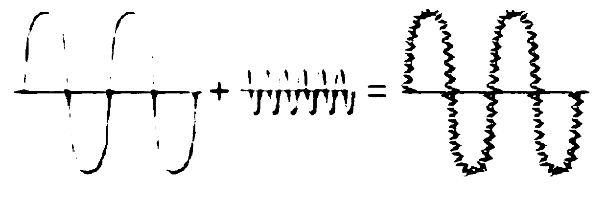
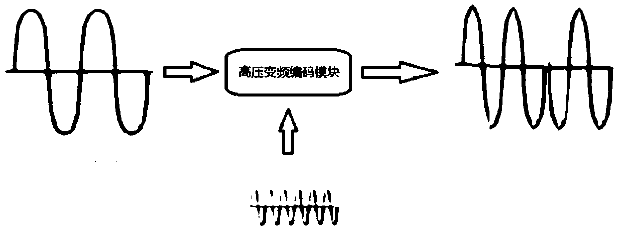
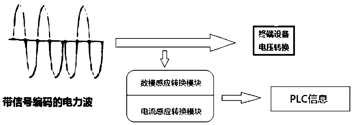
[0038] Please refer to figure 2 , image 3 , this application does not use the existing carrier communication method, but directly encodes and decodes the high-voltage power wave. The specific implementation process is as follows:
[0039] In this embodiment, the power line communication system includes a high-voltage variable-frequency coding module, and high-voltage power waves and PLC signals are input into the high-voltage variable-frequency coding module.
[0040] In this embodiment, the high-voltage power wave is 220V, 50Hz power wave, of course, it can also be a common 380V industrial power, or a high-voltage power wave that meets the transmission standards of other countries.
[0041] In this embodiment, the peak value of the PLC signal is 24V, of course, it can also be other common PLC signal peak values such as 12V or 36V.
[0042] The PLC signal is generally a sine wave signal, and its frequency is generally different from that of the power wave. To this end, ...
Embodiment 2
[0062] The difference of this embodiment relative to embodiment 1 is:
[0063] In this embodiment, the remote device receives the induced current signal after receiving the frequency conversion coded power wave. The current value of the power wave signal with encoded high and low changes is converted to 1 when it is higher than the first preset value, and converted to 0 when it is lower than the second preset value, thereby forming a digital signal similar to 001110....
[0064] In this application, the encoded power wave not only has a higher voltage amplitude, but also has a higher current amplitude, which makes it possible to determine the digital signal by detecting the change of the current value in this embodiment. The voltage value in the prior art is only 24V, and the voltage value transmitted to the destination after loss is only about 14V, and the current value is even negligible. It is almost impossible to achieve the purpose of converting digital signals by detecti...
Embodiment 3
[0067] In this embodiment, the remote device not only senses the voltage signal but also the current signal after receiving the frequency conversion coded power wave.
[0068] As described in Embodiment 1 or Embodiment 2, if the amplitude of the power wave is above 70V, the voltage sensing module will convert it to 1, and if the amplitude of the power wave is below 50V, the voltage sensing module will convert it to 0. The wave signal is converted into a digital signal of 11001····. When the current value is higher than the first preset value, it is converted to 1, and when it is lower than the second preset value, it is converted to 0, thereby forming a digital signal similar to 001110.... The digital signal converted by the voltage sensing module is called the first dimension signal. The digital signal converted by the current sensing module is called the second dimension signal.
[0069] Both the first-dimension signal and the second-dimension signal can be inversely encod...
PUM
 Abstract
Description
Claims
Application Information
 - R&D
- Intellectual Property
- Life Sciences
- Materials
- Tech Scout
- Unparalleled Data Quality
- Higher Quality Content
- 60% Fewer Hallucinations
Browse by: Latest US Patents, China's latest patents, Technical Efficacy Thesaurus, Application Domain, Technology Topic, Popular Technical Reports.
© 2025 PatSnap. All rights reserved.Legal|Privacy policy|Modern Slavery Act Transparency Statement|Sitemap|About US| Contact US: help@patsnap.com


