Block encoder and encoding method of polarization code
An encoding method and polar code technology are applied in the field of encoding devices and can solve the problems of high algorithm complexity and low processing speed.
- Summary
- Abstract
- Description
- Claims
- Application Information
AI Technical Summary
Problems solved by technology
Method used
Image
Examples
Embodiment 1
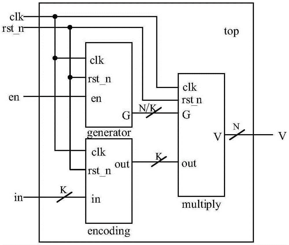
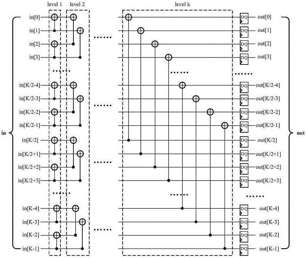
[0062] Figure 5 , 6 , 7 are respectively the input coding module that is example with the polar code block encoder of code length N=16, K=4, generate matrix module and multiplier module, the present invention uses G 16 Middle G 4 And the 4×4 zero matrix is a block, so that each clock of the information sequence inputs 4 information bits, and the operation result of the 4-bit signal and the 4×4 matrix block is stored in the lower four bits of the 16-bit register, and the second The clock then inputs 4 bits of information, and the operation result of the 4×4 matrix block is XORed according to the operation result of each row of the generation matrix and the corresponding 4 bits in the 16-bit register, and so on, according to the characteristics of the generation matrix The 4-bit input information of each clock and the operation result of the 4×4 matrix block are subjected to XOR operation, and the last 4-bit information bit input is selected and XOR operation is performed...
Embodiment 2
[0067] Assuming that the test input data is 1101_1111_0001_0101, the signal of the first clock entering the encoder is in[3:0]=1011, after a series of XOR operations in the input encoding module, the output of the module is out[0]=in [0]^in[1]^in[2]^in[3]=1, out[1]=in[1]^in[3]=0, out[2]=in[2]^in[ 3]=1, out[3]=in[3]=1, and generate G[0]=1 in the matrix module at the same time, G[1], G[2], G[3] save G in the shift register respectively [0], G[1], G[2] data, then G[3:0]=0001, the output of the above two modules is used as the input of the multiplier module, by Figure 7, a four-bit two-to-one multiplexer with G[0] as the selection terminal, since G[0]=1, the output terminal of the selector is 1101, then V[3:0]=1101, G[1] , G[2], G[3] are all 0, so the output of the selector with these three bits as the selector is 0000, so V[15:4]=0000_0000_0000, in summary V[15:0] =0000_0000_0000_1101; the input signal of the second clock is in[3:0]=1111, and the output of the input encoding m...
PUM
 Abstract
Description
Claims
Application Information
 - R&D
- Intellectual Property
- Life Sciences
- Materials
- Tech Scout
- Unparalleled Data Quality
- Higher Quality Content
- 60% Fewer Hallucinations
Browse by: Latest US Patents, China's latest patents, Technical Efficacy Thesaurus, Application Domain, Technology Topic, Popular Technical Reports.
© 2025 PatSnap. All rights reserved.Legal|Privacy policy|Modern Slavery Act Transparency Statement|Sitemap|About US| Contact US: help@patsnap.com


