
Control method of power network, devices and control system of power network

A technology of power network and control method, which is applied in the field of power, and can solve problems such as large demand and low utilization rate of production equipment

Active Publication Date: 2016-12-21
ENN SCI & TECH DEV
View PDF6 Cites 1 Cited by
  • Summary
  • Abstract
  • Description
  • Claims
  • Application Information

AI Technical Summary

Problems solved by technology

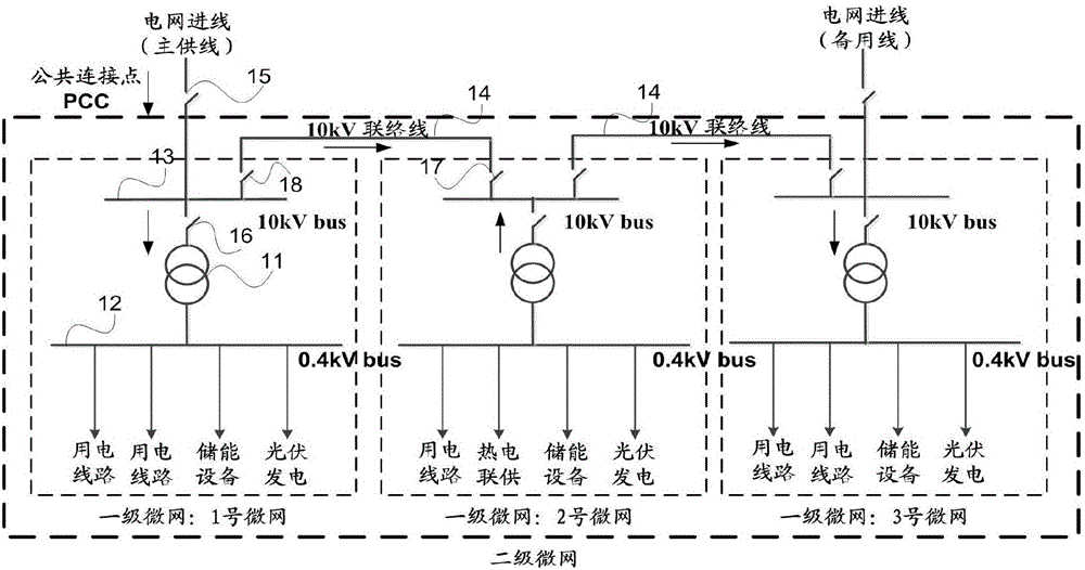
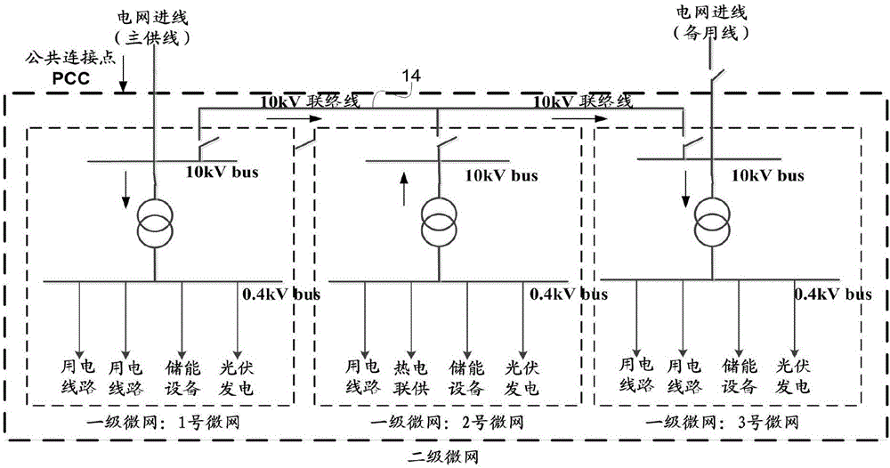
[0005] Embodiments of the present invention provide a method, device, and system for controlling a power network, in order to improve the problem of low utilization rate of production equipment or grid-connected micro-grid in the prior art in order to meet the supply and demand balance of grid-connected micro-grid To solve the problem of large demand on the power grid, a new power network is provided, and a control scheme for micro-grid power in the power network is provided

Method used


Image

  • Control method of power network, devices and control system of power network
  • Control method of power network, devices and control system of power network
  • Control method of power network, devices and control system of power network

Examples


Embodiment 1

[0072] An embodiment of the present invention provides a control method for the above electric power network, refer to Figure 6 As shown, the specific steps include:

[0073] S601. For each microgrid group, the network scheduling device acquires real-time power of PCCs of the microgrid group.

[0074] Since the positive and negative directions and positive and negative signs of power / current are stipulated in this embodiment, when the active power, reactive power, and current of the grid-connected point of the primary microgrid are positive, it means that the power / current is positive At this time, the power / current flows from the second-level microgrid to the first-level microgrid; when the power / current of the grid-connected point of the microgrid is negative, it means that the power / current is reversed, and the power / current flows from the first The primary microgrid flows to the secondary microgrid. However, the power of the PCC usually cannot be reversed, so the real-t...

Embodiment 2

[0105] This embodiment provides a method for controlling a power network, wherein the power network is the same as the above-mentioned power network. The following are specific steps of a method for controlling a power network provided by an embodiment of the present invention, refer to Figure 7 . The execution subject of each step may be a micro-grid control device.

[0106] S701 (optional): The micro-grid control device sends real-time operating parameters of the micro-grid controlled by the micro-grid control device to the network scheduling device.

[0107] The microgrid control device periodically (1-5 seconds) refreshes the real-time operating parameters of the microgrid it controls, and sends the real-time operating parameters to the network dispatching device.

[0108] If the PCC of the microgrid is connected to the power grid, the microgrid control device sends the real-time power parameters of the PCC of the microgrid to the network scheduling device; otherwise, t...

Embodiment 3

[0134] An embodiment of the present invention provides a network scheduling device for use in a power network. The power network is the above-mentioned power network. The device can be software or hardware. The implementation of each functional module can refer to the first embodiment above. Here No longer. Such as Figure 10 As shown, the device includes:

[0135] The obtaining unit 101 is used for the network scheduling device to obtain the real-time power of the PCC of the microgrid group;

[0136] a sending unit 102, configured to send, by the network scheduling device, a first control command to at least one microgrid control device if the real-time power of the PCC acquired by the acquiring unit 101 is greater than the maximum power threshold of the PCC, the The first control command is used to increase the reverse power of the microgrid controlled by the microgrid control device, or reduce the forward power of the microgrid; and / or, if the PCC acquired by the acquisit...


PUM


Abstract

The invention relates to a control method of a power network, devices and a control system of the power network and belongs to the electric power field. The objective of the invention is to solve the problem of low utilization ratio of energy generation devices caused by the satisfaction of the balance of supply and demand of grid-connected microgrids or the large demand of the grid-connected microgrids for a power grid in the prior art. The control method includes the following steps that: N microgrids are divided into M microgrid groups, wherein each microgrid is connected with the other microgrids in the N microgrids through connection lines, and each microgrid is communicated with a power grid power supply through a point of common coupling (PCC); a network dispatching device acquires the real-time power of the PCCs of the microgrid groups; and if the real-time power of the PCCs is larger than the maximum power threshold value of the PCCs, the network dispatching device sends a first control command to at least one microgrid control device, and / or if the real-time power of the PCCs is smaller than the maximum power threshold value of the PCCs, the network dispatching device sends a second control command to at least one microgrid control device.

Description

technical field [0001] The invention relates to the field of electric power, in particular to a control method, device and system for a power network. Background technique [0002] Due to its high efficiency, cleanliness, and flexibility, distributed energy can complement traditional energy sources. Micro-grid, also known as micro-grid and micro-grid, is an important utilization method of distributed energy. It is a system mainly composed of load and production equipment (mainly including distributed power generation equipment). A microgrid can either be connected to an external grid or run in isolation. [0003] refer to figure 1 As shown, the microgrid running in parallel with the grid is a grid-connected microgrid, which is characterized by internal production equipment and loads, and the grid through a public connection point (also called a public connection point, which can be referred to as PCC: point of common coupling) connected. [0004] The grid-connected micro...

Claims


Application Information

Patent Timeline
Patent Type & Authority Applications(China)
IPC IPC(8): H02J3/38H02J3/32H02J3/06
CPCH02J3/06H02J3/32H02J3/38
Inventor 舒鹏朱江艳王学博
Owner ENN SCI & TECH DEV
Learn More