
Air curtain protecting device of labyrinth machine tool spindle

A protection device and machine tool spindle technology, which is applied to mechanical equipment, engine components, engine sealing, etc., can solve the problems of difficult processing of air curtain protection devices, increase path length and difficulty, simplify processing difficulty, and improve protection degree Effect

Active Publication Date: 2016-12-21
BEIJING CTB SERVO CO LTD
View PDF10 Cites 14 Cited by
  • Summary
  • Abstract
  • Description
  • Claims
  • Application Information

AI Technical Summary

Problems solved by technology

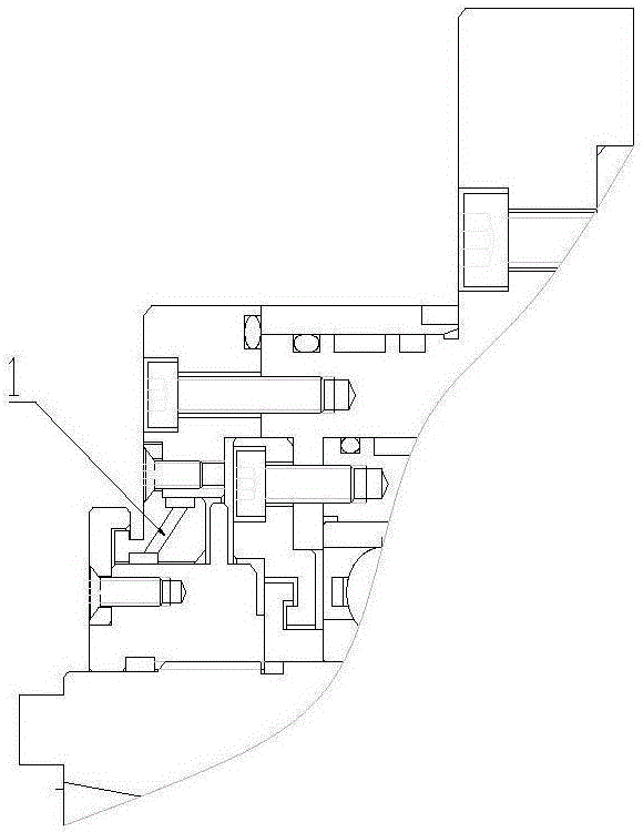
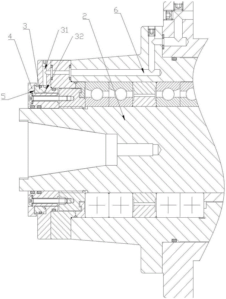
[0004] In order to solve the above-mentioned problems in the prior art, that is, in order to solve the problem that the traditional air curtain protection device is difficult to process, the present invention provides a labyrinth machine tool spindle air curtain protection device, the air curtain protection device includes The end cover on the main shaft of the machine tool is provided with a first air flow passage in the end cover, one end of the first air flow passage communicates with the air inlet, and the other end communicates with the second air flow passage in the end cover, the The end cover includes a labyrinth disc and a labyrinth seat, and in an assembled state, the labyrinth disc is nested in the labyrinth seat and thus forms the second airflow channel between the labyrinth disc and the labyrinth seat, Gas enters the first airflow channel from the air inlet and is discharged through the second airflow channel; the air curtain protection device further includes a sealing cover, and the sealing cover cooperates with the end cover to form a third airflow passage, the third airflow passage communicates with the second airflow passage

Method used


Image

  • Air curtain protecting device of labyrinth machine tool spindle
  • Air curtain protecting device of labyrinth machine tool spindle
  • Air curtain protecting device of labyrinth machine tool spindle

Examples


Embodiment Construction

[0021] Preferred embodiments of the present invention are described below with reference to the accompanying drawings. Those skilled in the art should understand that these embodiments are only used to explain the technical principles of the present invention, and are not intended to limit the protection scope of the present invention. For example, although various components in the drawings are drawn in a specific scale, such a proportional relationship is only exemplary, and those skilled in the art can make adjustments as needed so as to adapt to specific applications.

[0022] It should be noted that, in the description of the present invention, the terms "center", "upper", "lower", "left", "right", "vertical", "horizontal", "inner", "outer" etc. The indicated orientation or positional relationship is based on the orientation or positional relationship shown in the drawings, and is only for the convenience of describing the present invention and simplifying the description...


PUM


Abstract

The invention belongs to the technical field of mechanical seal and particularly relates to an air curtain protecting device of a labyrinth machine tool spindle. The device provided by the invention aims to solve the problem that a conventional air curtain protecting device is great in machining difficulty. In order to solve the problem, the air curtain protecting device provided by the invention comprises an end cover mounted on the machine tool spindle, wherein a first air flow channel is formed in the end cover, one end of the first air flow channel communicates to an air inlet while the other end of the first air flow channel communicates to a second air flow channel in the end cover, and the end cover comprises a labyrinth disc and a labyrinth base, the labyrinth disc is inlaid in the labyrinth base and therefore, the second air flow channel is formed between the labyrinth disc and the labyrinth base; gas enters the first air flow channel from the air inlet and is discharged from the second air flow channel. The air curtain protecting device further comprises a seal cover, wherein the seal cover is matched with the end cover to form a third air flow channel which communicates with the second air flow channel. A chute is machined on the radial bevel of the labyrinth disc to form an exhaust vent, so that the machining difficulty of the air curtain protecting device is simplified to a great extent.

Description

technical field [0001] The invention belongs to the field of mechanical seals, and specifically provides a labyrinth type machine tool spindle air curtain protection device. Background technique [0002] The core supporting part of the main shaft of the machining center is the high-speed and precise main shaft bearing. Any tiny impurities entering the main shaft bearing will affect the working accuracy and life of the main shaft bearing, so the sealing characteristics of the bearing are very important. Air curtain protection, commonly known as air seal, is mainly used for bearing protection to prevent external cutting fluid, iron filings and other dirt from entering the bearing and causing damage to the bearing. The traditional air curtain protection needs to lead an air source into the front end cover, and then install the device with multiple inclined holes into the front end cover, and the gas is discharged from the gap between the main shaft and the front end cover throu...

Claims


Application Information

Patent Timeline
Patent Type & Authority Applications(China)
IPC IPC(8): F16J15/40F16J15/447B23B19/02
CPCB23Q1/70F16J15/406F16J15/447
Inventor 项久鹏孙健
Owner BEIJING CTB SERVO CO LTD
Learn More