
Patsnap Eureka
For R&D, Patsnap Eureka makes reading and utilizing patents & technical documents easy.
Patsnap Eureka AIR
Designed for self-driven R&D workflows. Generate viable solutions, solve complex R&D challenges, empower your innovation with AI.

Patsnap Eureka Materials
Designed for material experts only. Revolutionize your material R&D, from search, analyze, to developing new materials.

TechResearch
Generate reliable direction feasibility study reports for your R&D in just a few steps.

TechSeek
Discover and master advanced knowledge NOW. Basics, ideas, possibilities, all at once.

TechMind
As an expert in R&D Theories, TechMind can generates customized viable solutions instantly.

TechRisk
Analyze your overall solution with one click, know your potential R&D risks in advance.

TechMonitor
Get weekly tech updates, stay abreast of the latest tech innovations and key insights.
Radial cages for high speed bearings
A cage, axial technology, applied in the direction of bearings, shafts and bearings, bearing components, etc., can solve problems such as bearing failure, reducing bearing fatigue strength, lubricating film tearing, etc.
- Summary
- Abstract
- Description
- Claims
- Application Information
AI Technical Summary
Problems solved by technology
Method used
Image

Examples
Embodiment Construction
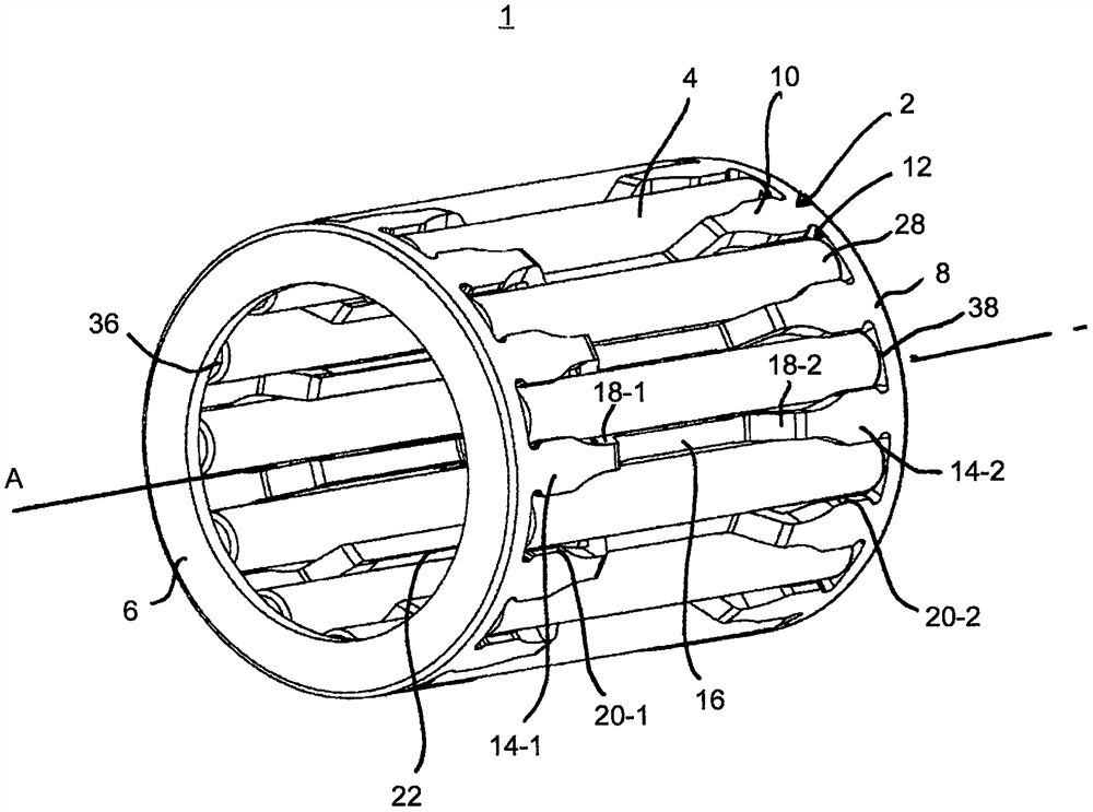
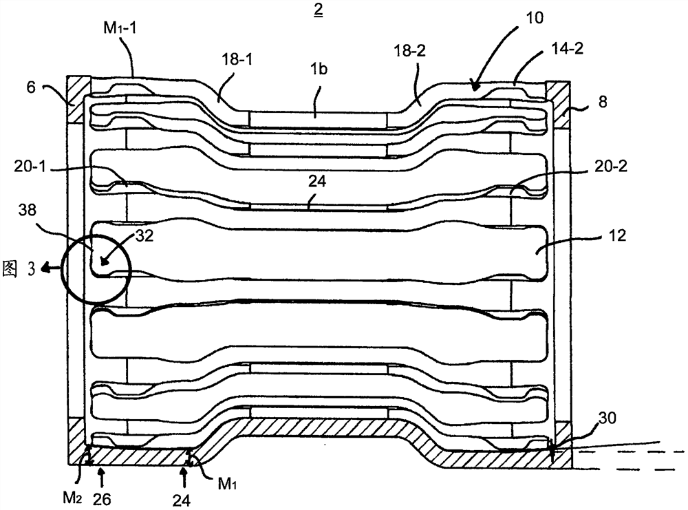
[0021] figure 1 A perspective view of a needle roller cage assembly 1 is shown, comprising a radial cage 2 and a roller 4 inside the radial cage. The radial cage 2 also has a first side ring and a second side ring 6, 8, which have a certain distance in the axial direction and are connected to each other by an axial beam 10, between which there is a space for accommodating the rollers 4. 12 pocket holes. remove figure 1 In addition to figure 2 It can be seen that the axial cross member 10 itself has side sections 14 - 1 , 14 - 2 which are respectively connected to the side rings 6 , 8 . In addition, the axial cross member 10 has a central section 16 which is connected to the side sections 14-1, 14-2 via lateral connection sections 18-1, 18-2. Wherein the side sections 14 - 1 , 14 - 2 and the middle section 16 are axial, and the connecting sections 18 - 1 , 18 - 2 are inclined to the rotation axis A of the bearing 1 .
[0022] The limit flanges 20, 22 installed on the side...
PUM
 Abstract
Description
Claims
Application Information
 - R&D Engineer
- R&D Manager
- IP Professional
- Industry Leading Data Capabilities
- Powerful AI technology
- Patent DNA Extraction
Browse by: Latest US Patents, China's latest patents, Technical Efficacy Thesaurus, Application Domain, Technology Topic, Popular Technical Reports.
© 2024 PatSnap. All rights reserved.Legal|Privacy policy|Modern Slavery Act Transparency Statement|Sitemap|About US| Contact US: help@patsnap.com