
Anti-corrosion hydraulic oil tank for tractor

A technology of hydraulic oil tank and tractor, which is applied to mechanical equipment, fluid pressure actuating device, fluid pressure actuating system components, etc., can solve the problems of insufficient filtering force of hydraulic oil tank, affecting power transmission effect and high maintenance cost, etc. To achieve the effect of easy assembly and manufacturing process, rapid filtration and good effect

Active Publication Date: 2018-07-06
山东博创瑞天制冷技术有限公司
View PDF7 Cites 0 Cited by
  • Summary
  • Abstract
  • Description
  • Claims
  • Application Information

AI Technical Summary

Problems solved by technology

The above-mentioned first method can realize the normal operation of the hydraulic device, but the disadvantage is that the waste of hydraulic oil is serious and the maintenance cost is high.
The disadvantage of the second method is that it takes a long time, which affects normal use, and the impurities are brought back when the hydraulic oil is returned, and some impurities are suspended in the hydraulic oil, which cannot be removed only by standing. The filtering power of the hydraulic oil tank is not strong enough, which affects the power transmission effect, and the operation is unstable, which affects safe operation

Method used


Image

  • Anti-corrosion hydraulic oil tank for tractor
  • Anti-corrosion hydraulic oil tank for tractor

Examples


Embodiment Construction

[0014] In order to further understand the content, features and effects of the present invention, the following examples are given, and detailed descriptions are given below with reference to the accompanying drawings.

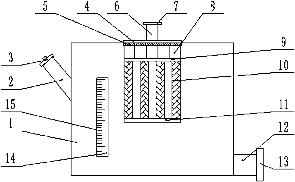
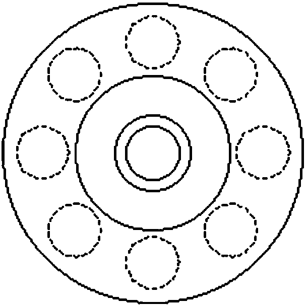
[0015] Combine below Figure 1-2 The structure of the hydraulic oil tank for the tractor of the present invention is described in detail. A hydraulic oil tank for anti-corrosion tractors, comprising a tank body 1, the upper left end of the tank body 1 is fixedly connected to the fuel filler port 2, the upper end of the fuel filler port 2 is fixedly connected to the fuel filler cap 3, and the upper end of the tank body 1 It is fixedly connected with the cleaning cover 4, the lower end of the cleaning cover 4 is fixedly connected with the sealing ring 5, the sealing ring 5 is in close contact with the box body 1, and the middle of the cleaning cover 4 is passed through the oil return port 6, so The upper end of the oil return port 6 is fixedly connected with th...


PUM


Abstract

The invention relates to a corrosion resistant hydraulic oil tank for a tractor. The corrosion resistant hydraulic oil tank comprises a tank body, wherein the upper end of the left side of the tank body is fixedly connected with an oil filling port, the upper end of the oil filling port is fixedly connected with an oil filling cover, the upper end of the tank body is fixedly connected with a cleaning cover, the lower end of the cleaning cover is fixedly connected with a sealing ring, the sealing ring makes close contact with the tank body, an oil return port penetrates through the middle of the cleaning cover, the upper end of the oil return port is fixedly connected with a flange of the oil return port, the inner upper end of the tank body is fixedly connected with a connecting column, the other end of the connecting column is fixedly connected with a shunting plate, the shunting plate is fixedly connected with the oil return port, the lower end of the shunting plate is fixedly connected with a plurality of filter screens, the lower ends of the filter screens are fixedly connected with a support plate, and the lower side of the right end of the tank body is fixedly connected with an oil outlet. Therefore, the invention provides the hydraulic oil tank which has the advantages of high filtering capability, high filtering speed, good effect, simple structural design, easiness in assembly and manufacturing and convenience in installation.

Description

technical field [0001] The invention belongs to the field of general machinery, in particular to a hydraulic oil tank for anti-corrosion tractors. Background technique [0002] For many hydraulic machines, hydraulic oil is the source of power for their work. However, after a long period of use, a large number of impurities will appear in the hydraulic oil, resulting in turbidity of the hydraulic oil, which will lead to a decrease in work efficiency and affect the normal operation of the hydraulic machine. [0003] It is necessary to frequently pump out the hydraulic oil from the hydraulic equipment, and then replace it with new hydraulic oil. Or after the hydraulic oil is pumped out, put it in a container for a period of time, and after a period of standing, the impurities therein will sink to the bottom, and then the clarified hydraulic oil will be pumped out and returned to the hydraulic device. Although the above-mentioned first method can realize the normal operation o...

Claims


Application Information

Patent Timeline
Patent Type & Authority Patents(China)
IPC IPC(8): F15B21/04B01D29/52
CPCB01D29/52F15B21/041
Inventor 王静
Owner 山东博创瑞天制冷技术有限公司
Learn More