
High-strength turbine blade

A steam turbine blade, high-strength technology, which is applied to the supporting elements of the blade, non-polymer organic compound adhesives, mechanical equipment, etc. Damage and other problems, to achieve the effect of improving anti-corrosion effect, improving safety and effectiveness, and good stability

Active Publication Date: 2016-12-21
南京赛达科技有限公司
View PDF7 Cites 8 Cited by
  • Summary
  • Abstract
  • Description
  • Claims
  • Application Information

AI Technical Summary

Problems solved by technology

[0002] The steam turbine blade is an important part of the steam turbine generator set. The steam turbine blades commonly used in the market generally improve the working efficiency by changing the shape of the blade, but the effect is not obvious, and the maximum working efficiency of the blade has not been exerted. And the existing steam turbine Blades are expensive to manufacture, susceptible to corrosion damage, short service life, and high maintenance costs

Method used


Image

  • High-strength turbine blade

Examples


Embodiment 1

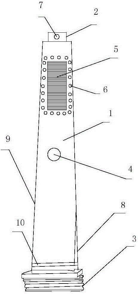
[0024] This embodiment provides a high-strength steam turbine blade with a structure such as figure 1 As shown, it includes a blade surface 1, a blade root 3 and a blade crown 2, the upper part of the blade surface 1 is connected to the blade crown 2, and the blade crown 2 is provided with a through hole 7, and the lower part is connected to the blade root 3 through a connector 10, and the blade root 3 A fir tree-shaped leaf root is adopted, and a square gas-gathering channel 5 is arranged on the blade surface 1, and ventilation holes 6 are arranged around the square gas-gathering channel 5, and a tendon hole 4 is arranged in the middle of the blade surface 1, and each side of the blade surface 1 is provided with The air inlet side 8 and the air outlet side 9, the width of the blade surface 1 decreases from the blade root 3 to the blade crown 2, the height of the blade surface is 900mm, and the blade surface is made of high-strength steel;

[0025] The surface of the steam tur...

Embodiment 2

[0033] This embodiment provides a high-strength steam turbine blade with a structure such as figure 1 As shown, it includes a blade surface 1, a blade root 3 and a blade crown 2, the upper part of the blade surface 1 is connected to the blade crown 2, and the blade crown 2 is provided with a through hole 7, and the lower part is connected to the blade root 3 through a connector 10, and the blade root 3 A fir tree-shaped leaf root is adopted, and a square gas-gathering channel 5 is arranged on the blade surface 1, and ventilation holes 6 are arranged around the square gas-gathering channel 5, and a tendon hole 4 is arranged in the middle of the blade surface 1, and each side of the blade surface 1 is provided with The air inlet side 8 and the air outlet side 9, the width of the blade surface 1 decreases from the blade root 3 to the blade crown 2, the height of the blade surface is 900mm, and the blade surface is made of high-strength steel;

[0034] The surface of the steam tur...


PUM


Abstract

The invention discloses a high-strength turbine blade. The high-strength turbine blade comprises a blade surface, a blade root and a blade top, wherein the upper part of the blade surface is connected with the blade top; the lower part of the blade surface is connected with the blade root through a connecting piece; a square air concentration channel is arranged on the blade surface; air vents are formed around the square air concentration channel; a lacing hole is formed in the middle part of the blade surface; the width of the blade surface is gradually decreased from the blade root to the blade top; and the blade surface is manufactured through high-strength steel. According to the high-strength turbine blade, the manufacturing cost is low, the working efficiency is high, and the strength is high.

Description

technical field [0001] The invention relates to the technical field of steam turbine blade devices, in particular to a high-strength steam turbine blade. Background technique [0002] The steam turbine blade is an important part of the steam turbine generator set. The steam turbine blades commonly used in the market generally improve the working efficiency by changing the shape of the blade, but the effect is not obvious, and the maximum working efficiency of the blade has not been exerted. And the existing steam turbine The blades are expensive to manufacture, are easily damaged by corrosion, have a short service life, and are expensive to maintain. Contents of the invention [0003] The technical problem to be solved by the present invention is to provide a steam turbine blade with low manufacturing cost, high work efficiency, anti-rust and high strength for the above shortcomings of the prior art. [0004] The technical solution of the present invention to solve the ab...

Claims


Application Information

Patent Timeline
IPC IPC(8): F01D5/14C09J4/02C09J4/06C09J11/06C09D1/00C09D7/12C09D133/00C22C38/06C22C38/04C22C38/02C22C38/18C22C38/12C22C38/16C22C38/10C22C38/08C22C38/14
CPCC08L2205/02C08L2205/035C09D1/00C09D133/00C09J4/06C09J11/06C22C38/001C22C38/002C22C38/005C22C38/02C22C38/04C22C38/06C22C38/105C22C38/12C22C38/14C22C38/16C22C38/18F01D5/141F01D5/147C08L23/0853
Inventor 刘达王河平宗国翼
Owner 南京赛达科技有限公司
Learn More