
Ultrasonic variable-frequency blockage removing, oil outlet increasing and injection increasing device

An ultrasonic and plugging-removing technology, which is applied in cleaning equipment, wellbore/well parts, earthwork drilling and production, etc., can solve problems such as difficult to meet the needs of deep plugging removal, short-circuit damage of electrical system, low electro-acoustic conversion efficiency, etc., to achieve The effect of reducing power, reducing acoustic wave loss, and improving electroacoustic conversion efficiency

Active Publication Date: 2016-12-21
HEILONGJIANG EAIEN NEW MATERIAL TECH DEV CO LTD
View PDF6 Cites 3 Cited by
  • Summary
  • Abstract
  • Description
  • Claims
  • Application Information

AI Technical Summary

Problems solved by technology

However, the electroacoustic conversion efficiency of existing ultrasonic plugging removal devices is low, and the effective radius of action is small, which is difficult to meet the needs of deep plugging removal
In addition, after the pressure balance rubber cylinder leaks in the ultrasonic reading device in the prior art, external oil, water and other liquids will enter the cavity where the piezoelectric ceramic is located, which will cause short-circuit damage to the electrical system and make it difficult to replace after damage

Method used


Image

  • Ultrasonic variable-frequency blockage removing, oil outlet increasing and injection increasing device
  • Ultrasonic variable-frequency blockage removing, oil outlet increasing and injection increasing device
  • Ultrasonic variable-frequency blockage removing, oil outlet increasing and injection increasing device

Examples


Embodiment Construction

[0024] The present invention will be further described below in conjunction with accompanying drawing:

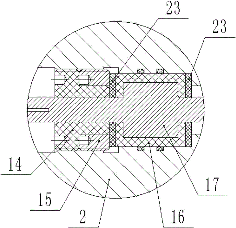
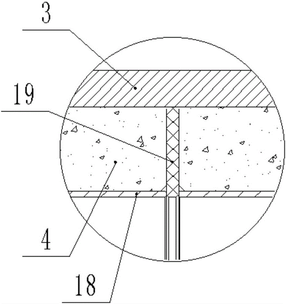
[0025] The ultrasonic frequency conversion deblocking and oil increasing device includes a cable 1, a cable connector 2, a protection cylinder 3, a piezoelectric ceramic 4 and a pressure balance rubber cylinder 11, and also includes a sealing piston 8. The cable 1 is connected to the On the upper side of the cable connecting body 2 , the protective tube 3 is fixedly connected to the outside of the lower end of the cable connecting body 2 .

[0026] The piezoelectric ceramic 4 is pre-tightened and fixed on the inner side of the protective tube 3 through the gland 12. Compared with the way of installing the piezoelectric ceramic 4 with a transition medium, the piezoelectric ceramic 4 is directly pre-tightened and fixed on the inner wall of the protective tube 3, which can The ultrasonic waves are emitted directly, which reduces the sound wave loss of the transition medium, im...


PUM


Abstract

The invention belongs to the technical field of oil production, and particularly relates to an ultrasonic variable-frequency blockage removing, oil outlet increasing and injection increasing device. The ultrasonic variable-frequency blockage removing, oil outlet increasing and injection increasing device comprises a cable, a cable connecting body, a protection cylinder, piezoelectric ceramic and a pressure balance rubber cylinder and further comprises a sealing piston. The cable is connected to the upper side of the cable connecting body through a cable connector assembly. The protection cylinder is fixedly connected to the outer side of the lower end of the cable connecting body. The piezoelectric ceramic is pre-tightened and fixed to the inner side of the protection cylinder through a gland, and copper skin is attached to the inner wall of the piezoelectric ceramic and connected with the cable through a wire and the cable connector assembly, so that power supply is achieved. A wire passing pipe is mounted in the center of the lower end of the cable connector body. The wire penetrates through the center of the wire passing pipe and a wire passing hole in the pipe wall of the wire passing pipe. The sealing piston is mounted in a piston sleeve and can slide in the piston sleeve, and the piston sleeve is connected to the lower end of the protection cylinder through a middle connecting body. The pressure balance rubber cylinder is of a cylindrical structure with the two ends being open.

Description

technical field [0001] The invention belongs to the technical field of oil recovery, and in particular relates to an ultrasonic frequency conversion device for increasing oil production and increasing injection. Background technique [0002] In the process of oilfield development and production, the underground environment will become increasingly complex. From drilling to completion to oil production and water injection, various production stimulation measures (such as acidizing, fracturing, downhole operation of oil and water wells, downhole overhaul, etc.), make oil and water wells suffer from foreign solid phase invasion, water sensitive damage, acid sensitive damage, untouchables Damage, particle migration, structure, bacterial clogging and other damages will cause changes in the seepage space of the oil-water layer, reduce the effective permeability, reduce the liquid production rate, and even completely blockage and stop production. [0003] Ultrasonic oil layer trea...

Claims


Application Information

Patent Timeline
Patent Type & Authority Applications(China)
IPC IPC(8): E21B37/00
CPCE21B37/00
Inventor 王纯刘防修李悦宁
Owner HEILONGJIANG EAIEN NEW MATERIAL TECH DEV CO LTD
Learn More