


Quick Research
Generate reliable direction feasibility study reports for your R&D in just a few steps.

Technical Q&A
Discover and master advanced knowledge NOW. Basics, ideas, possibilities, all at once.

Find Solutions
As an expert in R&D theories, this can generate solutions to your technical problems instantly.

Evaluate Feasibility
Analyze your overall solution with one click, know your potential R&D risks in advance.

Monitor Landscape
Get weekly tech updates, stay abreast of the latest tech innovations and key insights.
A mechanical arm and a garbage transfer vehicle
A technology of robotic arms and garbage cans, applied in the field of sanitation vehicles, can solve the problems that the robotic arms are easily damaged and affect the service life of garbage transfer vehicles, and achieve the effect of ensuring service life and avoiding damage.
- Summary
- Abstract
- Description
- Claims
- Application Information
AI Technical Summary
Problems solved by technology
Method used
Image

Examples
Embodiment 1
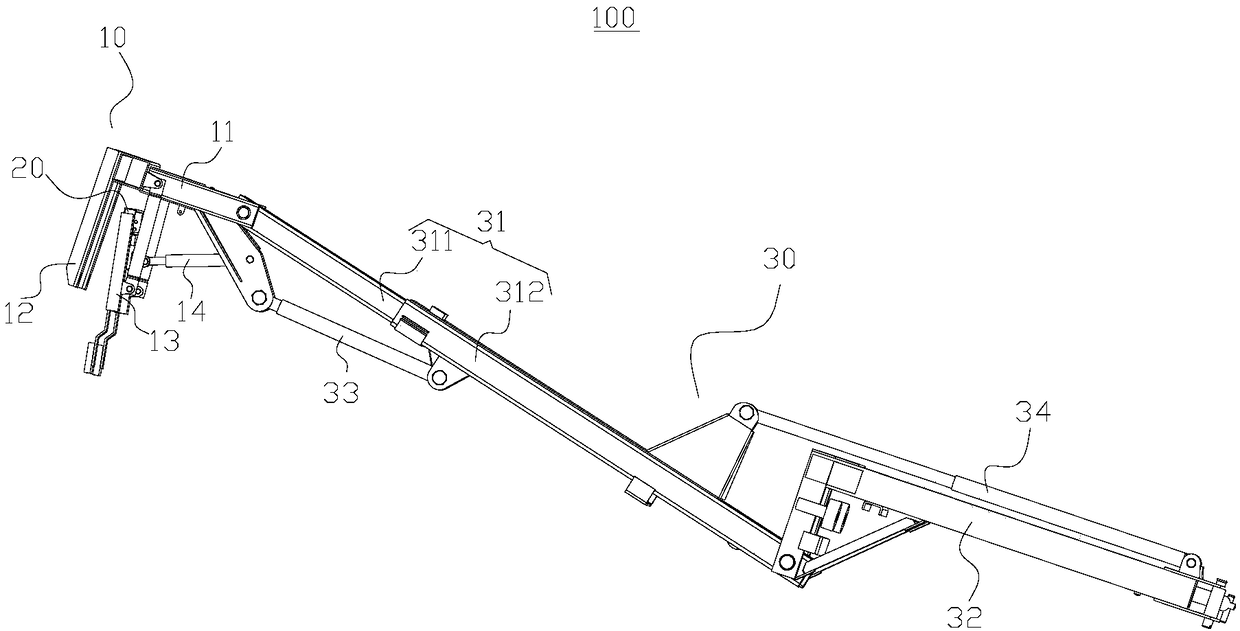
[0047] like figure 1 As shown, the present invention provides a mechanical arm 100 including a clamping mechanism 10 , a weighing device 20 and a turning mechanism 30 .
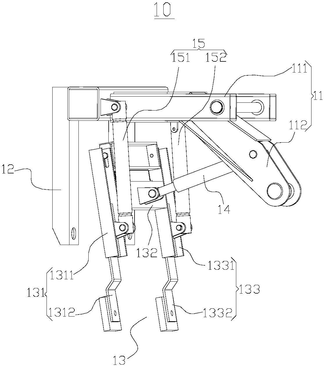
[0048] Among them, such as figure 2 Shown, clamping mechanism 10 comprises frame 11, is positioned at the fixed pressing frame 12 of dustbin inner side, is positioned at the movable pressing frame 13 of dustbin outside, first driving device 14 and second driving device 15, fixed pressing frame 12 and machine The frame 11 is fixedly connected, the movable press frame 13 is rotatably connected with the frame 11 , and the first driving device 14 is used to drive the movable press frame 13 to rotate and make the movable press frame 13 approach or move away from the fixed press frame 12 .
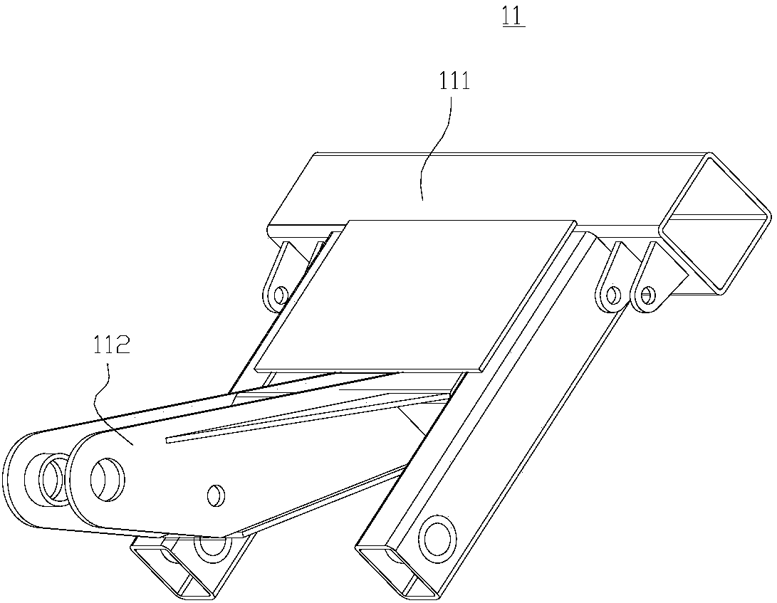
[0049] In this example, if image 3 As shown, the frame 11 includes a frame body 111 and a connecting portion 112 , the connecting portion 112 is fixedly connected to the frame body 111 , and the connecting portion 112 and t...
Embodiment 2
[0073] like Figure 12 As shown, the embodiment of the present invention provides a garbage transfer vehicle 200, including a vehicle body 201, a compartment 202, a sixth hydraulic cylinder 203, a control device and the mechanical arm 100 in the above-mentioned embodiments.
[0074] Wherein, the carriage 202 is a hollow structure, and the top of the carriage 202 has a pouring port 2021 , and the carriage 202 is installed on the rear side of the carriage body 201 .
[0075] like Figure 13 As shown, the junction of the first horizontal part 3211 and the second horizontal part 3221 in the mechanical arm 100 is rotatably connected with the car body 201, and the car body 201 is provided with an arc guide rail 2011, and the first vertical part 3212 in the mechanical arm 100 And the second vertical part 3222 is provided with a slide block 2012, the slide block 2012 can slide along the arc guide rail 2011, the cylinder body of the sixth hydraulic cylinder 203 is hinged with the vehi...
PUM
 Abstract
Description
Claims
Application Information
 - R&D Engineer
- R&D Manager
- IP Professional
- Industry Leading Data Capabilities
- Powerful AI technology
- Patent DNA Extraction
Browse by: Latest US Patents, China's latest patents, Technical Efficacy Thesaurus, Application Domain, Technology Topic, Popular Technical Reports.
© 2024 PatSnap. All rights reserved.Legal|Privacy policy|Modern Slavery Act Transparency Statement|Sitemap|About US| Contact US: help@patsnap.com