An intelligent speed-regulating multifunctional patient transfer device
A technology of transfer device and intelligent speed regulation, which is applied in the direction of hospital beds, medical science, hospital equipment, etc., can solve the problems of difficulty in movement, falling off of pipes, and large manpower consumption, so as to ensure comfort and safety, reduce the number of adjustments, The effect of reducing work intensity
- Summary
- Abstract
- Description
- Claims
- Application Information
AI Technical Summary
Problems solved by technology
Method used
Image
Examples
specific Embodiment approach
[0029] DETAILED DESCRIPTION OF THE PREFERRED EMBODIMENTS: The present invention will be further described below in conjunction with the accompanying drawings.
Embodiment approach 1
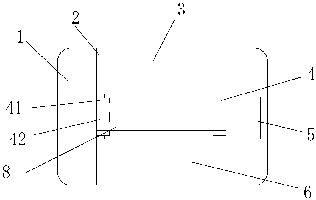
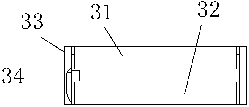
[0031] like figure 1 , image 3 , Figure 4 and Figure 5 As shown, an intelligent speed-regulating multifunctional patient transfer device includes a board body 1, and the board body 1 is provided with a mounting groove 11, and an upper guide rail unit 21 is arranged on the upper part of the side wall of the mounting groove 11, and is installed The bottom of the side wall of the groove is provided with a lower rail unit 22, the upper rail unit 21 and the lower rail unit 22 are symmetrically arranged, the upper rail unit 21 is provided with an upper sliding unit 3, and the lower sliding rail 22 is provided with a lower sliding unit 6. The installation groove 11 is also provided with a driving unit 4 for driving the relative movement of the upper sliding unit and the lower sliding unit, and a bearing bracket 7 is arranged between the upper sliding unit 3 and the lower sliding unit 6, and the Pressure sensors 9 and 10 are arranged on the left and right sides of the carrier tr...
Embodiment approach 2
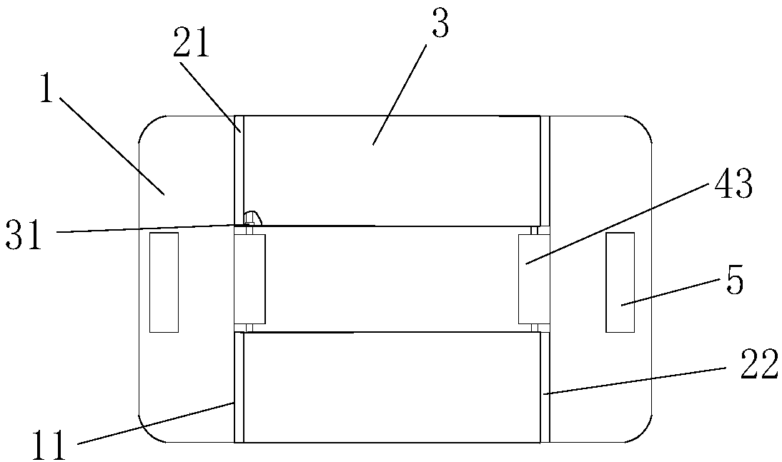
[0038] like figure 2 , image 3 , Figure 4 and Figure 5 As shown, an intelligent speed-regulating multifunctional patient transfer device includes a board body 1, and the board body 1 is provided with a mounting groove 11, and an upper guide rail unit 21 is arranged on the upper part of the side wall of the mounting groove 11, and is installed The bottom of the side wall of the groove is provided with a lower rail unit 22, the upper rail unit 21 and the lower rail unit 22 are symmetrically arranged, the upper rail unit 21 is provided with an upper sliding unit 3, and the lower sliding rail 22 is provided with a lower sliding unit 6. The installation groove 11 is also provided with a driving unit 4 for driving the relative movement of the upper sliding unit and the lower sliding unit, and a bearing bracket 7 is arranged between the upper sliding unit 3 and the lower sliding unit 6, and the Pressure sensors 9 and 10 are arranged on the left and right sides of the carrier t...
PUM
 Abstract
Description
Claims
Application Information
 - R&D
- Intellectual Property
- Life Sciences
- Materials
- Tech Scout
- Unparalleled Data Quality
- Higher Quality Content
- 60% Fewer Hallucinations
Browse by: Latest US Patents, China's latest patents, Technical Efficacy Thesaurus, Application Domain, Technology Topic, Popular Technical Reports.
© 2025 PatSnap. All rights reserved.Legal|Privacy policy|Modern Slavery Act Transparency Statement|Sitemap|About US| Contact US: help@patsnap.com


