
Power Component Lock Mounting Equipment

A technology for power components and installation equipment, which is applied in the field of power component locking and installation equipment, can solve problems such as unstable installation and uncertain position of power components, and achieve the effects of accurate center positioning, digital positioning, and easy installation

Active Publication Date: 2018-10-26
PENGLAI POWER SUPPLY CO OF STATE GRID SHANDONG ELECTRIC POWER CO
View PDF6 Cites 0 Cited by
  • Summary
  • Abstract
  • Description
  • Claims
  • Application Information

AI Technical Summary

Problems solved by technology

Stimulated by the investment plan, there is basically no suspense about the performance growth of the power equipment industry in the next two years. Unlike other sectors that benefit from the investment-driven concept, the two major power grids announced the investment quota at the first time, which guaranteed the benefits of the power equipment industry. ; But with the development of science and technology, the installation of power components is uncertain and unstable, so we need a new lock installation equipment for power components

Method used


Image

  • Power Component Lock Mounting Equipment
  • Power Component Lock Mounting Equipment
  • Power Component Lock Mounting Equipment

Examples


Embodiment Construction

[0018] The following will clearly and completely describe the technical solutions in the embodiments of the present invention with reference to the accompanying drawings in the embodiments of the present invention. Obviously, the described embodiments are only some, not all, embodiments of the present invention. Based on the embodiments of the present invention, all other embodiments obtained by persons of ordinary skill in the art without making creative efforts belong to the protection scope of the present invention.

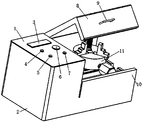
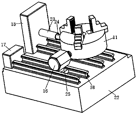
[0019] see Figure 1-4 , the present invention provides a technical solution: including a casing 2; a control panel 1 is provided on one side of the top surface of the casing 2; a protective cover 8 is provided on the other side of the top surface of the casing 2; One side of the front of the shell 2 is provided with a side plate 10; the casing 2 is provided with a workbench 22 on the back of the side plate 10; the top side of the workbench 22 is provided with...


PUM


Abstract

The invention discloses locking installation equipment for electric power components. The locking installation equipment comprises an enclosure, wherein a control panel is arranged at one side of the top surface of the enclosure and a protective cover is arranged at the other side of the top surface of the enclosure; a side plate is arranged at one side of the front surface of the enclosure; the enclosure is provided with a work bench at the back surface of the side plate; a hydraulic oil tank is arranged at one side of the top surface of the work bench; a bidirectional hydraulic cylinder is connected to the central position of one side surface of the hydraulic oil tank; a hydraulic rod is arranged on the top surface of the other end of the bidirectional hydraulic cylinder; the other end of the hydraulic rod is connected with a chuck base; a central circular hole is formed in the central position of the top surface of the chuck base; three jaw grooves are uniformly distributed in the top surface of the chuck base; a chuck jaw is arranged in each jaw groove; a motor is arranged at the other side of the arc side surface of the chuck base; a sliding rail a is arranged at the bottom side of the motor; and a sliding rail b is arranged at the bottom side of the chuck base. A three-jaw chuck is formed by the chuck base and the chuck jaws, fastening and disassembling are controlled through the motor and locating and locking are convenient and fast.

Description

technical field [0001] The invention relates to the technical field of power equipment, in particular to power component locking and installation equipment. Background technique [0002] The power system is a network composed of generators, transformers, transmission lines, and electrical equipment (loads), which includes all equipment connected in the network by electrical or mechanical means; these interconnected elements in the power system can be divided into two types: Class: one is power components, the other is control components, power components produce electric energy (generator), transform (power transformer), transmit and distribute (power transmission line, distribution network), consume (load); power equipment The manufacturing industry generally includes four sub-industries: power generation equipment industry, power transmission and transformation primary equipment industry, secondary equipment industry, and power environmental protection industry. The devel...

Claims


Application Information

Patent Timeline
Patent Type & Authority Patents(China)
IPC IPC(8): H05K7/14H05K7/12
CPCH05K7/12H05K7/1461
Inventor 季翠娜杨世盛王德刚丁镇张道升于凤举张轩焜张远铭孙世军张通永王兵王斌郝先廷张志王名科姜浩
Owner PENGLAI POWER SUPPLY CO OF STATE GRID SHANDONG ELECTRIC POWER CO
Learn More