
A wireless charging device and method

A wireless charging and rotating device technology, which is applied in the direction of circuit devices, battery circuit devices, current collectors, etc., can solve problems such as inaccurate user alignment, reduced charging efficiency, and poor user experience, and achieves solutions to inaccurate alignment, Effect of reducing energy loss and shortening charging time

Active Publication Date: 2016-12-14
ANKER INNOVATIONS TECH CO LTD
View PDF5 Cites 22 Cited by
  • Summary
  • Abstract
  • Description
  • Claims
  • Application Information

AI Technical Summary

Problems solved by technology

Therefore, as far as the existing wireless charging equipment is concerned, users are prone to misalignment during use.
Inaccurate alignment will greatly reduce charging efficiency and poor user experience
[0004] Therefore, the slow charging speed has become a relatively large complaint point in current wireless charging products

Method used


Image

  • A wireless charging device and method
  • A wireless charging device and method
  • A wireless charging device and method

Examples


specific Embodiment approach 3

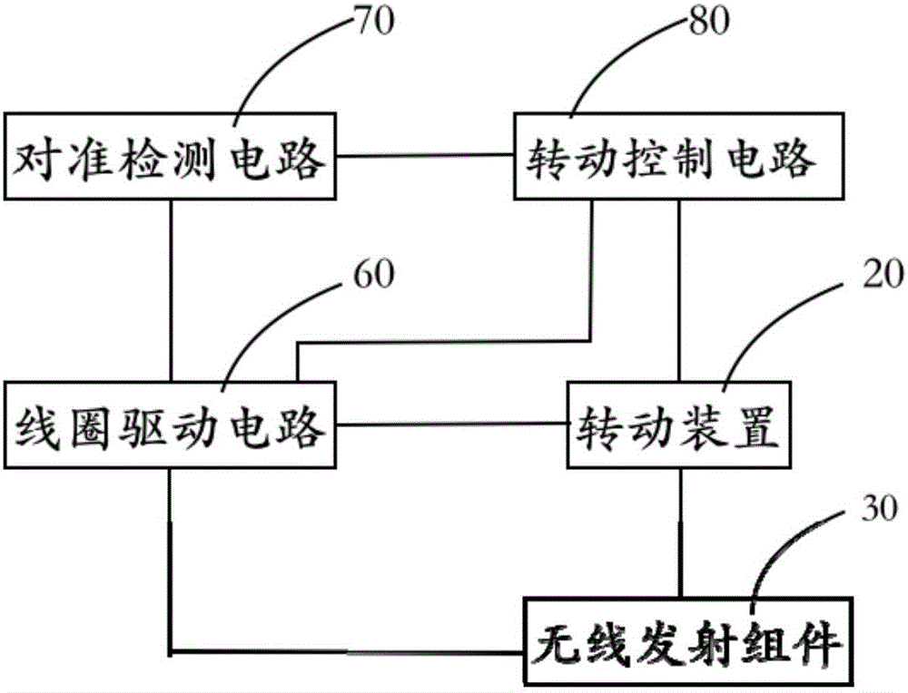
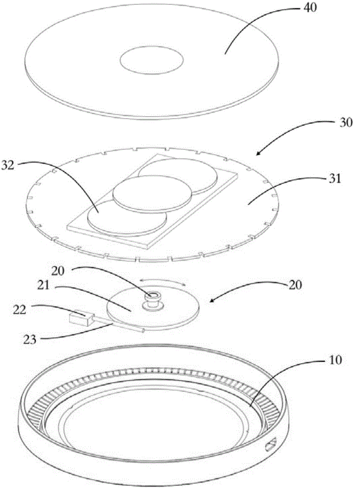
[0045] Such as image 3 As shown, a schematic diagram of an exploded perspective view of a wireless charging device according to Embodiment 3 of the invention. The third embodiment includes: a lower body cover 10 , a rotating device 20 , a wireless transmitting component 30 and an upper body cover 40 . The rotating device 20 is installed in the lower body cover 10 and is fixedly connected with the wireless transmission component 30 , and the upper body cover 40 is assembled with the lower body cover 10 .

[0046] Wherein, the rotating device 20 includes: a gear 21 , a motor 22 and a transmission member 23 ; the motor 22 drives the gear 21 to rotate through the transmission member 23 . Specifically, a connecting piece 211 is provided at the axial center of the gear 21 , and the gear 21 has a plurality of serrations (not shown) on the edge, and the serrations and the serrations (not shown) of the transmission member 23 are engaged with each other. When the transmission member ...

specific Embodiment approach 4

[0056] For more details in Embodiment 4, please refer to Embodiment 1, and details are not repeated here.

[0057] Specific Embodiments of the Invention: Detect the charging parameters of the charging coil. When the charging parameters do not match the preset reference, the position of the charging coil is automatically adjusted until the charging parameter matches the preset reference, that is, the charging coil Align with the device to be charged. At this time, the charging efficiency of the charging device is the highest, the energy consumption is the least, and the charging time is also the shortest.


PUM


Abstract

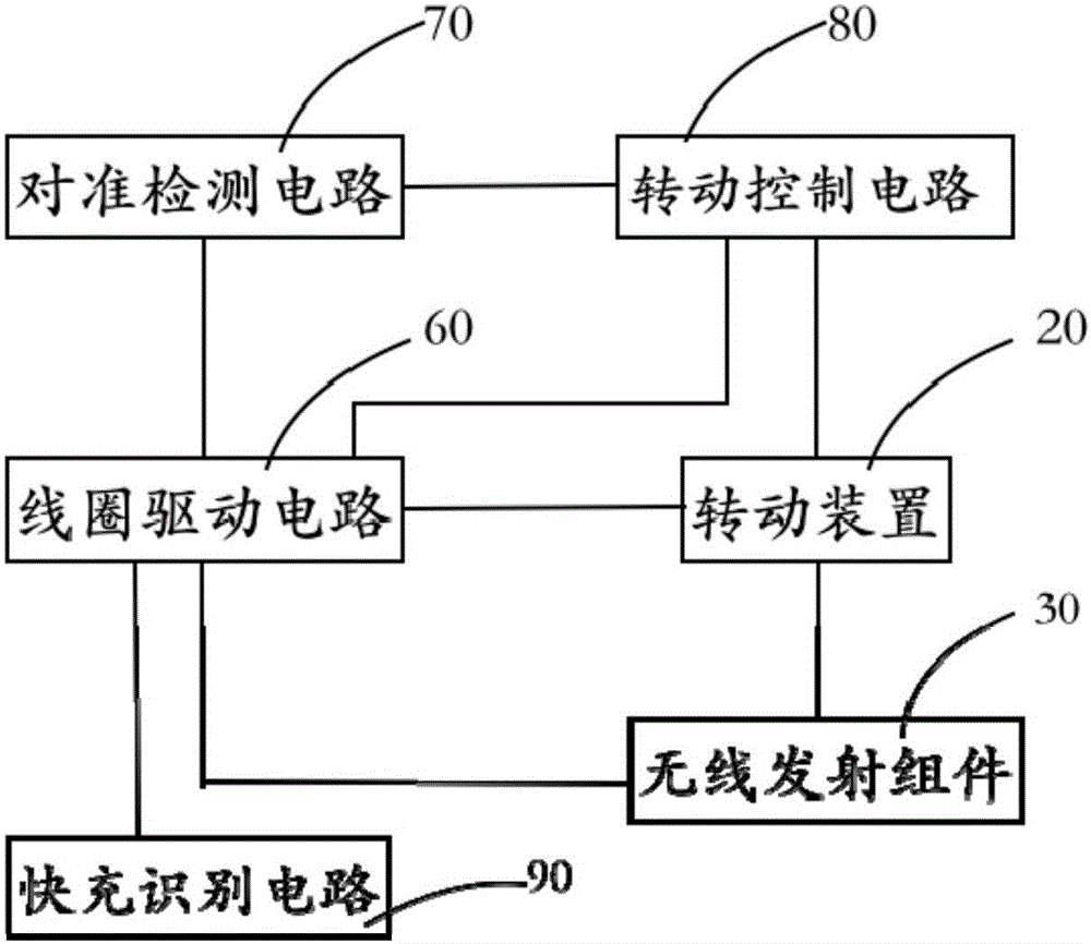
The invention relates to a wireless charging device and method. The wireless charging device comprises a coil drive circuit for driving a charging coil to operate; and an alignment detection circuit for detecting a charging parameter in the coil drive circuit, determining that the charging coil and a to-be-charged device to be aligned when a charging parameter matches a preset reference and keeping charging at the present position.When the charging parameter does not match the preset reference, a rotation control circuit is trigger to begin working. The wireless charging device also comprises a rotation control circuit used for controlling the rotation apparatus to rotate after being triggered by the alignment detection circuit; and a rotation apparatus used to rotate under driving of the rotation control circuit and triggering the coil drive circuit to begin working after the rotation is stopped. According to the embodiment of the present invention, the position of the charging coil is automatically adjusted by detecting the charging parameter of the charging coil, thereby solving the problem of misregistration between the wireless charging device and the to-be-charged device, improving the charging efficiency, reducing energy loss and shortening the charging time .

Description

【Technical field】 [0001] The invention relates to the technical field of charging, in particular to a wireless charging device and a method thereof. 【Background technique】 [0002] With the continuous evolution and development of electronic technology, wireless charging devices are now relatively popular in the market. [0003] However, since the wireless charging technology uses inductive charging between coils, the charging device and the device to be charged do not need to be connected by wires. Therefore, as far as the existing wireless charging point equipment is concerned, it is easy for users to have misalignment during use. Inaccurate alignment will greatly reduce charging efficiency and poor user experience. [0004] Therefore, the slow charging speed has become a relatively large complaint point in current wireless charging products. 【Content of invention】 [0005] The technical problem to be solved by the present invention is to provide a wireless charging de...

Claims


Application Information

Patent Timeline
Patent Type & Authority Applications(China)
IPC IPC(8): H02J7/00H02J50/10
CPCH02J5/005H02J7/025
Inventor 黄祖斌刘伟生
Owner ANKER INNOVATIONS TECH CO LTD
Learn More