
Planar antenna array and polar antenna with polarization regulation function

A flat-panel antenna array and horizontal polarization technology, which is applied in antenna arrays, antenna arrays that are energized separately, and antennas, can solve the problems of inability to achieve dual-polarization simultaneous compatibility, high antenna manufacturing costs, and low equivalent surface-to-surface efficiency. , to achieve the effect of smooth impedance, wide cavity wall and widened frequency band

Inactive Publication Date: 2016-12-14
NANJING CLEANWAVE COMM TECH
View PDF5 Cites 6 Cited by
  • Summary
  • Abstract
  • Description
  • Claims
  • Application Information

AI Technical Summary

Problems solved by technology

Usually live TV satellites and communication broadcasting satellites work in the state of dual-polarization or dual-circular polarization, while most of the current flat-panel array antennas work in the state of single-linear polarization or single-circular polarization. In order to achieve dual-polarization reception, it is often necessary to rotate The entire antenna panel, or use two antennas to send and receive two polarized signals respectively. These two methods are either complex in structure and cannot achieve dual-polarization compatibility at the same time, or the antenna manufacturing cost is high and the equivalent surface efficiency is low.

Method used


Image

  • Planar antenna array and polar antenna with polarization regulation function
  • Planar antenna array and polar antenna with polarization regulation function
  • Planar antenna array and polar antenna with polarization regulation function

Examples


Embodiment 1

[0070] Example 1 Single-line polarization signal reception

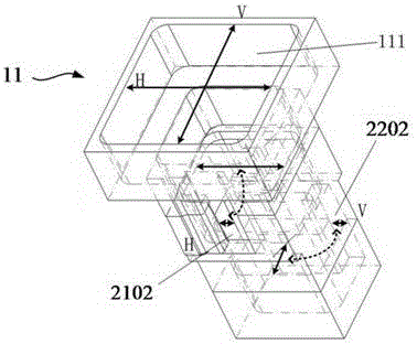
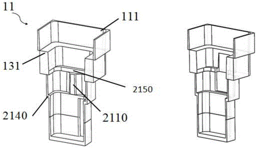
[0071] The direction of the incoming wave is single linear polarization E, and the polarization direction is arbitrary. The linear polarization wave can be decomposed into two in-phase linear polarization components according to the two polarization directions of the dual polarization radiation unit, which are respectively the horizontal polarization component E h And the vertical polarization component E v , The horizontal polarization component E received by the dual polarization antenna unit 11 h It is sent to the horizontally polarized signal transmission channel 21 through the horizontally polarized feeder port 2102 located under the unit, and finally collected to the horizontally polarized signal feeder port 2130 and transmitted to the polarized synthesizer 3, which is also received by the dual-polarized antenna unit 11. The vertical polarization component E v It is sent to the vertical polarization signal transmiss...

Embodiment 2

[0073] Example 2 Single-line polarization signal transmission

[0074] Contrary to the single-wire polarization reception process, the transmission signal provided by the back-end radio frequency circuit is sent to the common port 53 of the polarization connection port 51 or 52 of the polarizer 5, and sent to the polarization synthesizer 3 through the waveguide 4 Common port. At this time, the polarization synthesizer 3 plays the role of polarization decomposition. The transmitted signal is decomposed into two orthogonal linear polarization signals and enters the horizontal through the two polarization connections 32 and 33 of the polarization synthesizer 3 respectively. The polarized signal total feed port 2130 and the vertical polarized signal total feed port 2230 are distributed to the dual-polarized antenna unit 11 through the polarized signal transmission channel, and recombined at the waveguide opening 111 surface of each dual-polarized antenna unit , Thus completing the si...

Embodiment 3

[0075] Embodiment 3 Single circular polarization signal reception

[0076] The direction of the incoming wave is the single circularly polarized wave E, and the direction of polarization is arbitrary. Similar to the single-line polarized reception, the circularly polarized wave can be decomposed into horizontal polarization component E h And the vertical polarization component E v , E h And E v The two polarization components are equal in amplitude, and the phase difference is 90°. The horizontal polarization component E received by all dual-polarized antenna units 11 h Converged to the horizontally polarized signal total feed port 2130 through the horizontally polarized signal transmission channel 21, while the vertical polarized component E v It also converges at the vertical polarization signal total feed port 2230.

[0077] The horizontal polarization signal total feed port 2130 and the vertical polarization signal transmission channel 2230 total port are respectively connected t...


PUM


Abstract

The invention provides a planar antenna array. The planar antenna array comprises multiple open waveguide units and waveguide signal transmission channels; each signal transmission channel is equipped with a multi-stage one-to-two power distribution network, and adopts a reflective structure which consists of multiple slowly-changed stage structures and slowly-changed stages; the open waveguide units, waveguide openings, a first polarized selection cavity, a second polarized selection cavity, a first polarized connecting opening, and a second polarized connecting opening are combined with multiple stage structures and interference convex structures, so as to effectively realize impedance conversion and impedance matching and expand frequency band bandwidth; in addition, the requirement on the manufacturing precision is relatively low, and the manufacturing cost is even lower; in addition, the invention provides a polar antenna with a polarization regulation function on the basis; the polar antenna comprises the polar antenna array with the above-mentioned structure, and a polarization regulation apparatus; the polarization regulation apparatus comprises a polarization synthesizer and a polarization receiving-transmitting device, wherein the common ports of the polarization synthesizer and the polarization-taking device are directly connected; and the polarization-taking device rotates along an axial line, and realizes dual-polarization receiving-transmitting and sharing through a minute quantity of microwave reactive devices.

Description

Technical field [0001] The invention belongs to the technical field of microwave antennas, and particularly relates to an improved open waveguide, an antenna sub-array with the structure, a flat panel antenna array, and a flat panel antenna with polarization adjustment. Background technique [0002] Satellite communication has the advantages of long transmission distance, wide coverage, less interference, etc. With the rapid development of global informatization, more and more information is transmitted through satellites, and satellite communications on mobile carriers anytime, anywhere, has become military and civilian The urgent need for dual-use emergency communication and real-time communication. Vehicle-mounted (ship-borne or air-borne) satellite mobile communication systems are usually called "communication in motion". One of the core technologies of communication in motion is antenna technology. The antenna forms of communication in motion include reflector antennas, flat...

Claims


Application Information

Patent Timeline
Patent Type & Authority Applications(China)
IPC IPC(8): H01Q1/36H01Q15/24H01Q23/00H01Q21/06
CPCH01Q23/00H01Q1/36H01Q15/242H01Q21/061
Inventor 王岩吴知航王正斌陈茂明梁雄帆
Owner NANJING CLEANWAVE COMM TECH
Learn More