
Sub-band-processing-based clutter suppression method and apparatus for passive radar

An external radiation source radar and clutter suppression technology, which is applied in the field of external radiation source radar signal processing, achieves the effect of small calculation and strong robustness

Active Publication Date: 2016-12-14
WUHAN UNIV
View PDF3 Cites 16 Cited by
  • Summary
  • Abstract
  • Description
  • Claims
  • Application Information

AI Technical Summary

Problems solved by technology

However, there are significant differences between the subband clutter cancellation method of the present invention and the frequency domain ECA-B method in the core steps of clutter cancellation, specifically shown in: 1) The subband clutter cancellation method adopts frequency offset subspace expansion and delay subspace expansion are used to eliminate the adverse effects of non-ideal factors such as carrier frequency offset and fractional delay, but the frequency domain ECA-B method does not specifically consider this point; 2) The subband clutter cancellation method uses LS adaptive filtering To cancel clutter, LS adaptive filtering is related to the construction of oversampled clutter subspace, which is also different from the cancellation method in the frequency domain ECA-B method

Method used


Image

  • Sub-band-processing-based clutter suppression method and apparatus for passive radar
  • Sub-band-processing-based clutter suppression method and apparatus for passive radar
  • Sub-band-processing-based clutter suppression method and apparatus for passive radar

Examples


Embodiment 1

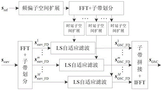
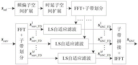
[0076]A method for suppressing radar clutter from external radiation sources based on subband processing in the present invention introduces the idea of ​​subband signal processing for radar clutter suppression from external radiation sources, and constructs clutter subspaces in an over-sampling manner, using LS Adaptive filtering to eliminate clutter, where the two inputs are the monitoring signal s surv and reference signal s ref , the output is the monitoring signal after clutter suppression. Include the following steps:

[0077] Step 1: Decompose the monitoring signal into multiple sub-band signals;

[0078] Step 2: Use the reference signal to construct the clutter subspace through frequency offset subspace expansion and delay subspace expansion, and perform subband decomposition. The frequency interval of frequency offset subspace expansion is smaller than the frequency resolution, and the delay interval of time delay subspace expansion is smaller than the subband Sign...

Embodiment 2

[0122] This embodiment 2 is a device embodiment. This embodiment 2 and the method embodiment 1 have the same technical concept of the invention. Please refer to the method embodiment 1 for the content not described in detail in the device embodiment 2.

[0123] Such as Figure 8 As shown in the present invention, a sub-band processing-based external radiation source radar clutter suppression device introduces the idea of ​​sub-band signal processing for external radiation source radar clutter suppression, and constructs clutter by oversampling In the wave subspace, LS adaptive filtering is used to cancel the clutter, where the two inputs are the monitoring signal s surv and reference signal s ref , the output is the monitoring signal after clutter suppression. Includes the following units:

[0124] A sub-band decomposing unit, configured to decompose the monitoring signal into multiple sub-band signals;

[0125] The clutter subspace construction unit is used to construct t...


PUM


Abstract

The invention discloses a sub-band-processing-based clutter suppression method and apparatus for a passive radar. The method comprises the four steps of sub band decomposition, over-sampling clutter sub space construction, LS adaptive filtering, and sub band synthesis. To be specific, a monitoring signal is composed into multi-path sub band signals; a clutter sub space is constructed in an over sampling mode by using a reference signal; sub band decomposition is carried out; LS adaptive filtering is carried out on each sub band; and then the filtered sub band signals are synthesized to obtain a monitoring signal after clutter suppression. According to the method, the robustness on non-ideal factors like a carrier frequency offset, a sampling rate frequency offset, a fractional delay, and a channel frequency response and the like is high; the clutter suppression performance is close to the theoretical upper limit; the calculation load is low; the parallel processing architecture is provided; and thus the method and apparatus are suitable for engineering real-time implementation and have the popularization and application values.

Description

technical field [0001] The invention relates to the technical field of external radiation source radar signal processing, in particular to a method and device for suppressing external radiation source radar clutter based on subband processing. Background technique [0002] External radiation source radar is a non-cooperative bistatic / multistatic radar system built on the basis of external radiation sources. Because the emission signal is unknown, two types of channels are often set in the external radiation source radar, namely the reference channel and the monitoring channel. The reference channel is used to collect the transmitted signal, and the purified reference signal is used as a reference and matching sample; the monitoring channel is used to receive the target scattering signal, and the channel output is called the monitoring signal. The direct path signal from the transmitting station to the receiving station is called a direct wave. Under ideal conditions, it is ...

Claims


Application Information

Patent Timeline
IPC IPC(8): G01S7/36
CPCG01S7/36
Inventor 易建新万显荣程丰
Owner WUHAN UNIV
Learn More