
Flexible Bionic Landing System and Its Application

A landing system and flexible technology, applied in the field of unmanned aerial vehicles, can solve the problems of difficult landing and recovery, and achieve the effects of improving landing adhesion, low production cost, and increasing contact area.

Active Publication Date: 2018-09-07
CHINA UNIV OF PETROLEUM (EAST CHINA)
View PDF4 Cites 0 Cited by
  • Summary
  • Abstract
  • Description
  • Claims
  • Application Information

AI Technical Summary

Problems solved by technology

[0008] The purpose of the present invention is to provide a flexible bionic landing system and its application to solve the above-mentioned problems of unmanned aerial vehicles in complex environments such as landing and recovery, so that unmanned aerial vehicles can land on complex ground, provide long-term monitoring and provide ground information support

Method used


Image

  • Flexible Bionic Landing System and Its Application
  • Flexible Bionic Landing System and Its Application
  • Flexible Bionic Landing System and Its Application

Examples


Embodiment 1

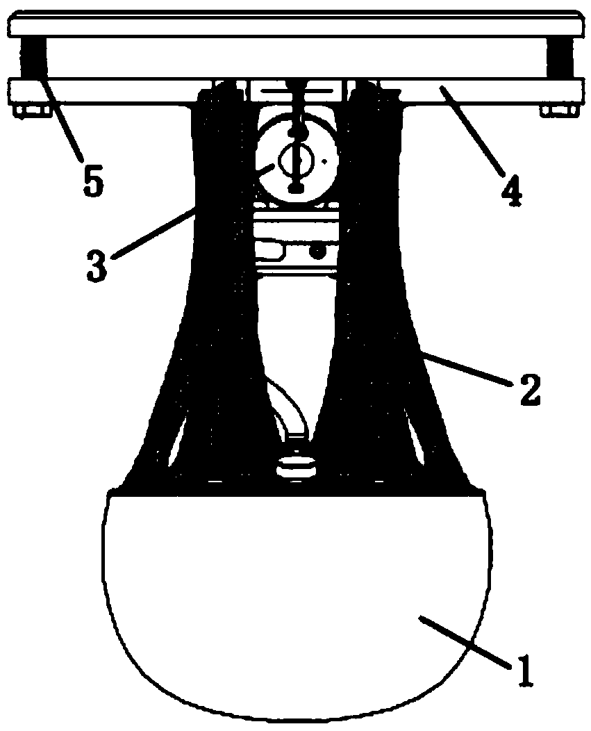
[0031] Embodiment one: see figure 1 , a flexible bionic landing system, comprising a bionic flexible landing device 1, a connection device connected above the bionic flexible landing device 1, and a buffer device connected to the connection device, the buffer device being located above the connection device. The bionic flexible landing device 1 is a hemispherical flexible body; the connection device includes a hollow connection body 2 and an air compression device 3 communicating with the hollow part of the connection body. The buffer device includes two layers of buffer bodies 4, and the two layers of buffer bodies are connected by springs 5.

[0032] In the flexible bionic landing system of this embodiment, the preparation method of the bionic flexible landing device is: under the conditions of 27°C and negative 0.2 atmospheric pressure, epoxy resin, carbon particles with a particle size of 0.8mm and p-hydroxybenzene The sulfonic acid was mixed and stirred for 2.5 hours acc...

Embodiment 2

[0036] Embodiment 2: A flexible bionic landing system, including a bionic flexible landing device and a connecting device connected above the bionic flexible landing device, the bionic flexible landing device is a hemispherical flexible body; the connecting device includes a hollow connecting body, And an air compression device communicating with the hollow part of the connecting body.

[0037] In the flexible bionic landing system of this embodiment, the preparation method of the bionic flexible landing device is: under the conditions of 28°C and negative 0.2 atmospheric pressure, epoxy resin, carbon particles with a particle size of 0.6mm and p-hydroxybenzene The sulfonic acid was mixed and stirred for 2.8 hours according to the weight ratio of 3.5:1:1 to make a hemispherical flexible body.

[0038] In the flexible bionic landing system of this embodiment, the connecting body is made of carbon fiber, and the air compression device is an air compression pump.

[0039] The fl...

Embodiment 3

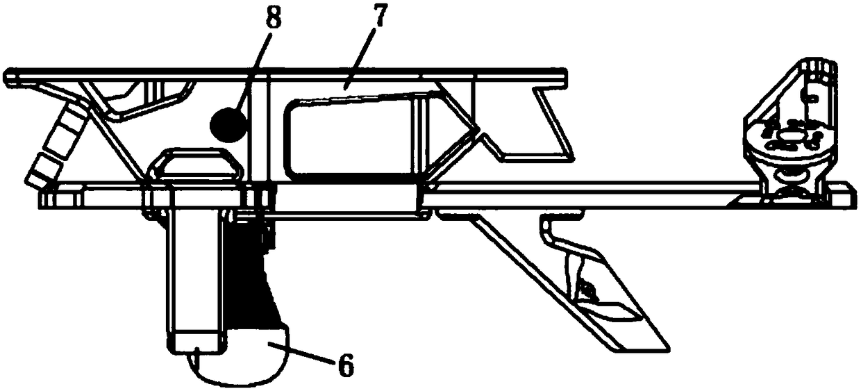
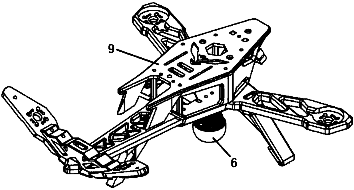
[0040] Embodiment three: see figure 2 , an unmanned aerial vehicle, comprising a flexible bionic landing system according to the first embodiment, the flexible bionic landing system 6 is installed under the fuselage of the unmanned aerial vehicle 7 . The flexible bionic landing system 6 is installed directly below the center of gravity 8 of the drone.

[0041] The UAV in this embodiment is suitable for landing in a simple environment, or a complex environment, or a landing area in a relatively complex environment.


PUM


Abstract

The invention relates to a flexible bionic landing system and its application. The flexible bionic landing system includes a bionic flexible landing device and a connecting device connected above the bionic flexible landing device. The bionic flexible landing device is a flexible body; the connecting device It includes a hollow connection body and an air compression device communicating with the hollow part of the connection body. The flexible bionic landing system of the present invention has a simple structure, is easy to maintain, and has low production costs. It adopts a flexible structure design to absorb the vibration of the body of the drone when it lands on a complex surface, and at the same time improves the landing adhesion. The flexible bionic landing system of the present invention is adopted The UAV of the landing system can land in complex terrain environments such as large slopes and high wet slippery, realize landing in complex terrain and provide long-term monitoring and ground information support, reducing the need for UAVs to land on flat and small slopes. Limitations of location landings.

Description

technical field [0001] The invention belongs to the technical field of unmanned aerial vehicles and relates to unmanned aerial vehicle landing technology, in particular to a flexible bionic landing system and its application. Background technique [0002] UAV is an unmanned aircraft operated by radio remote control equipment and its own program control device. It can be used for aerial reconnaissance, surveillance, communication, anti-submarine, electronic interference, etc. Power inspection, aerial photography and other fields, and play an important role. [0003] Due to the influence of environmental factors in the target area of ​​the UAV, the UAV cannot choose the landing point arbitrarily when it lands. In order to monitor the target area at close range, the UAV needs to select the landing point nearby in the target area. At present, When domestic and foreign drones land, they need to use ground signs to guide and assist in landing. However, due to the complex environm...

Claims


Application Information

Patent Timeline
Patent Type & Authority Patents(China)
IPC IPC(8): B64C25/32B64C25/56
CPCB64C25/32B64C25/56B64U70/60
Inventor 罗偲于雷健杨泽斌郭文尚杜金
Owner CHINA UNIV OF PETROLEUM (EAST CHINA)
Learn More