
Airplane forebody vortex flow control device

A flow control and precursor technology, which is applied in the direction of power plant, aircraft control, power plant layout/installation, etc., can solve the problems of reducing aircraft thrust, deterioration of intake/engine matching performance, and lower performance of air inlet, etc. Achieve the effect of reducing the flow field distortion index value, easy installation and maintenance, and remarkable effect

Inactive Publication Date: 2016-12-14
AVIC SHENYANG AERODYNAMICS RES INST
View PDF5 Cites 2 Cited by
  • Summary
  • Abstract
  • Description
  • Claims
  • Application Information

AI Technical Summary

Problems solved by technology

In modern aircraft, the airflow usually flows through the surface of the fuselage before entering the air inlet. Under certain flight conditions, body vortices and ridgeline vortices will be generated. If these precursor vortices are not controlled, their entry into the air inlet will inevitably lead to The reduction of airway performance and the increase of flow field distortion reduce the thrust of the aircraft and cause the deterioration of the matching performance of entry / exit
When the aircraft is flying, due to the ridgeline of the front fuselage and the layout of the intake duct, the precursor vortex induced by the front fuselage will be sucked into the intake duct, resulting in the deterioration of the quality of the inlet airflow of the intake duct, resulting in internal flow Separation, which in turn leads to a reduction in total pressure recovery and an increase in flow field distortion, which will have a negative impact on the matching of entry / exit and cause flight safety hazards

Method used


Image

  • Airplane forebody vortex flow control device

Examples


Embodiment 1

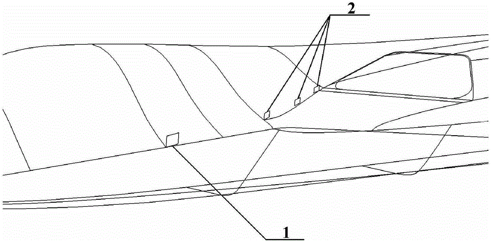
[0012] Such as figure 1 As shown, an aircraft precursor vortex flow control device includes a precursor vortex breaker 1 and three deflectors 2. The precursor vortex breaker 1 is installed above the ridge line of the aircraft precursor and in front of the inlet of the air intake along the flow direction. ; 3 deflectors 2 are sequentially installed behind the precursor vortex breaker 1, the original low-energy flow flows on the path, and guide the low-energy flow behind the precursor vortex breaker 1 so that it does not flow into the inlet of the air duct, Instead, it flows backward along the groove between the air intake cover and the fuselage. The height of the precursor vortex breaker 1 is equivalent to the height of the local vortex, and the length is 1.5 times of the height. The height of the deflector 2 is equivalent to the height of the local low-energy flow, the length is 1.8 times the height, and the angle between the installation angle and the original flow direction...


PUM


Abstract

An airplane forebody vortex flow control device comprises a forebody vortex knapper and a plurality of flow deflectors. The forebody vortex knapper is installed above the airplane forebody ridge and in front of an air intake duct inlet in the flow direction. The multiple flow deflectors are sequentially installed behind the forebody vortex knapper and on an original low energy flow direction path, guide low energy flow behind the forebody vortex knapper, and enable the low energy flow not to flow into the air intake duct inlet but to flow backwards along a groove between an air intake duct outer cover and a fuselage. The airplane forebody vortex flow control device is simple in structure, easy to install and maintain, and remarkable in flow control effect. In the typical flight state, the total pressure recovery coefficient of an air intake duct can be increased by 1% or above, and the value of the flow field distortion index show in the specification is reduced by 30% or above.

Description

technical field [0001] The invention belongs to the technical field of aviation aerodynamics, and in particular relates to an aircraft precursor vortex flow control device. Background technique [0002] As an important part of the propulsion system, the air intake will directly affect the performance of the engine and even the whole aircraft. In modern aircraft, the airflow usually flows through the surface of the fuselage before entering the air inlet. Under certain flight conditions, body vortices and ridgeline vortices will be generated. If these precursor vortices are not controlled, their entry into the air inlet will inevitably lead to The reduction of airway performance and the increase of flow field distortion reduce the thrust of the aircraft, resulting in the deterioration of the matching performance of entry / exit. When the aircraft is flying, due to the front fuselage ridgeline and the layout of the intake duct, the precursor vortex induced by the front fuselage ...

Claims


Application Information

Patent Timeline
IPC IPC(8): B64C21/02B64D33/02
CPCB64C21/02B64D33/02B64D2033/0226
Inventor 赵振山马晓光
Owner AVIC SHENYANG AERODYNAMICS RES INST
Learn More