
The connection structure between the a-pillar and the lower a-pillar of the vehicle body

A technology for connecting structures and car bodies, applied to superstructures, subassemblies of superstructures, vehicle parts, etc., can solve problems such as unfavorable cost, heavy weight of structural parts, etc., achieve good frontal and side collision effects, and extend Endurance mileage, reasonable design effect

Active Publication Date: 2018-12-28
奇瑞新能源汽车股份有限公司
View PDF8 Cites 0 Cited by
  • Summary
  • Abstract
  • Description
  • Claims
  • Application Information

AI Technical Summary

Problems solved by technology

At present, the common problem in the field of electric vehicles is that the battery life of electric vehicles is limited, which limits the promotion and application of electric vehicles
[0003] Most of the existing structural parts on the car body are steel plate structures, which are heavy, which is not conducive to the lightweight of electric vehicles, and is not conducive to effectively extending the cruising range of electric vehicles. Moreover, the manufacturing, assembly and maintenance costs of metal parts are high, which is not conducive to reducing costs and cannot meet energy saving requirements. Environmental protection requirements; in addition, the upper and lower structures of the A-pillar are two separate parts, and the two are connected by structural parts. In order to meet the requirements of frontal collision and side collision, the weight of the structural parts is heavy, and it is difficult to achieve both frontal and side collisions and weight simultaneously. take into account

Method used


Image

  • The connection structure between the a-pillar and the lower a-pillar of the vehicle body
  • The connection structure between the a-pillar and the lower a-pillar of the vehicle body
  • The connection structure between the a-pillar and the lower a-pillar of the vehicle body

Examples


Embodiment Construction

[0025] The specific implementation manner of the present invention will be described in further detail below by describing the embodiments with reference to the accompanying drawings.

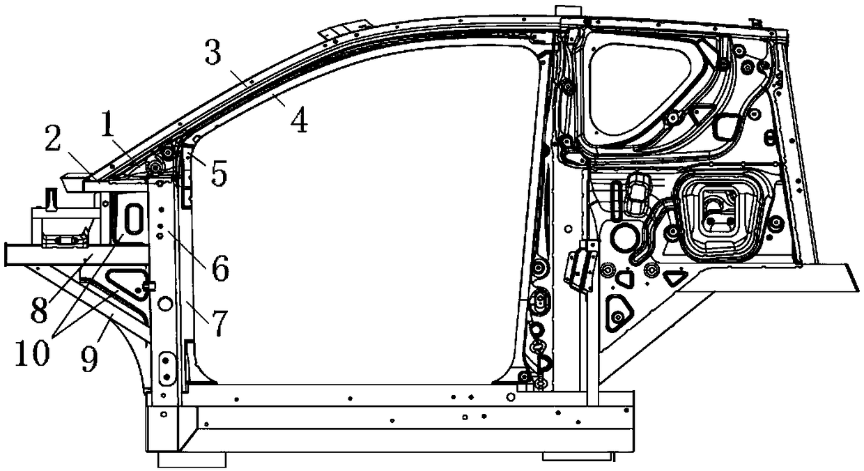
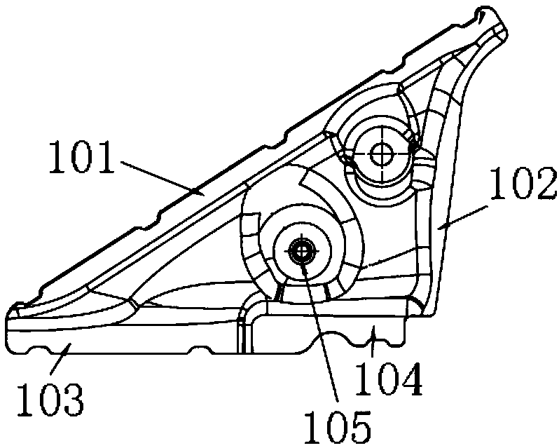
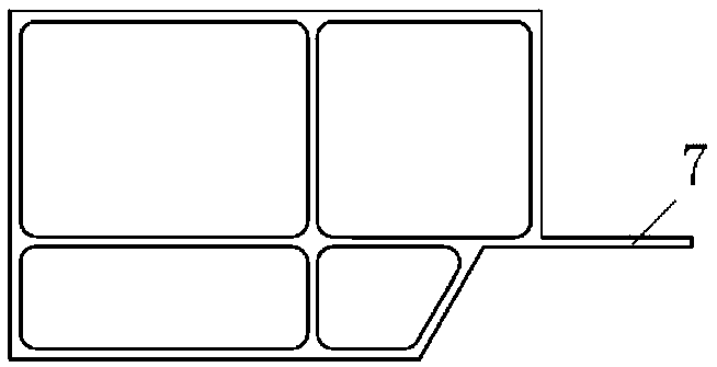
[0026] Such as Figure 1 to Figure 3 As shown, the connection structure between the A-pillar and the A-pillar of the vehicle body includes a connecting plate 1 and a connecting beam 2, the connecting beam 2 is a longitudinal beam, and the rear end of the connecting beam 2 is welded on the front side of the upper end of the A-pillar lower structure 6 , the other end of the connecting beam 2 is connected to the front end of the structure 3 on the A-pillar, the front surface of the structure on the A-pillar is a plane, and the plane is connected to the upper surface of the connecting beam by welding, and the front end of the structure on the A-pillar is fixed and formed at the same time. Reliable support, reasonable structure design, reliable connection and fixation.

[0027] The connecting plate...


PUM


Abstract

The invention discloses a connection structure between the A-pillar and the A-pillar of a vehicle body, which includes a connecting plate and a connecting beam. The connecting beam is a longitudinal beam. One end of the connecting beam is fixed on the front side of the upper end of the A-pillar lower structure, and the other end of the connecting beam Connected to the front end of the A-pillar upper structure, the connecting plate is a triangular plate, the upper edge of the connecting plate is connected to the A-pillar upper structure, and the lower edge of the connecting plate is connected to the connecting beam and the upper end of the A-pillar lower structure. The connection structure is reasonably designed and the connection is reliable. All parts are made of aluminum and are light in weight. It has good frontal impact and side impact effects. Both collision and weight can be taken into consideration at the same time. It is conducive to the lightweight of electric vehicles and can effectively extend the electric vehicle life. Car mileage.

Description

technical field [0001] The invention relates to the technical field of vehicle bodies, in particular to a connection structure between an A-pillar and a lower A-pillar of a vehicle body. Background technique [0002] As a new energy vehicle, electric vehicles have the advantages of energy saving and environmental protection. Electric vehicles are becoming more and more research hotspots in the automotive field. At present, the common problem in the field of electric vehicles is that the battery life of electric vehicles is limited, which limits the popularization and application of electric vehicles. [0003] Most of the existing structural parts on the car body are steel plate structures, which are heavy, which is not conducive to the lightweight of electric vehicles, and is not conducive to effectively extending the cruising range of electric vehicles. Moreover, the manufacturing, assembly and maintenance costs of metal parts are high, which is not conducive to reducing co...

Claims


Application Information

Patent Timeline
Patent Type & Authority Patents(China)
IPC IPC(8): B62D25/04
CPCB62D25/04
Inventor 吴怀华
Owner 奇瑞新能源汽车股份有限公司
Learn More