A micro-printer movement
What is Al technical title?
Al technical title is built by PatSnap Al team. It summarizes the technical point description of the patent document.
A micro-printer and core technology, applied in typewriters, printing devices, printing, etc., can solve the problems of easily damaged micro-printers, difficult disassembly, and printing paper folding, so as to eliminate the difficulty of disassembly, reduce paper jams, and eliminate gap effect
Active Publication Date: 2018-08-14
KONG YUE ELECTRONICS & INFORMATION IND XIN HUI
View PDF9 Cites 0 Cited by
Summary
Abstract
Description
Claims
Application Information
AI Technical Summary
This helps you quickly interpret patents by identifying the three key elements:
Problems solved by technology
Method used
Benefits of technology
Problems solved by technology
Existing micro-printer cores are generally assembled with sheet metal parts, and the paper passage is formed between the lower paper guide plate, the upper paper guide plate, the printing plate, and the paper feeding roller, and the paper passage is installed on the frame. It is a sheet metal part, and the lower end is difficult to make a smooth arc surface. After assembly, there is a large gap between the upper paper guide plate and the printing plate, which may easily cause folding, twisting, or even paper jamming of the printing paper, which will affect the user's use.
In addition, the paper passing assembly consisting of the upper paper guide plate, printing plate, and paper feeding roller is usually fixed on the frame by screws, which is difficult to disassemble and even more difficult to assemble. Great inconvenience to users
Method used
Image
Click on the blue label to locate the original text in one second.
Reading with bidirectional positioning of images and text.
Examples
Embodiment Construction
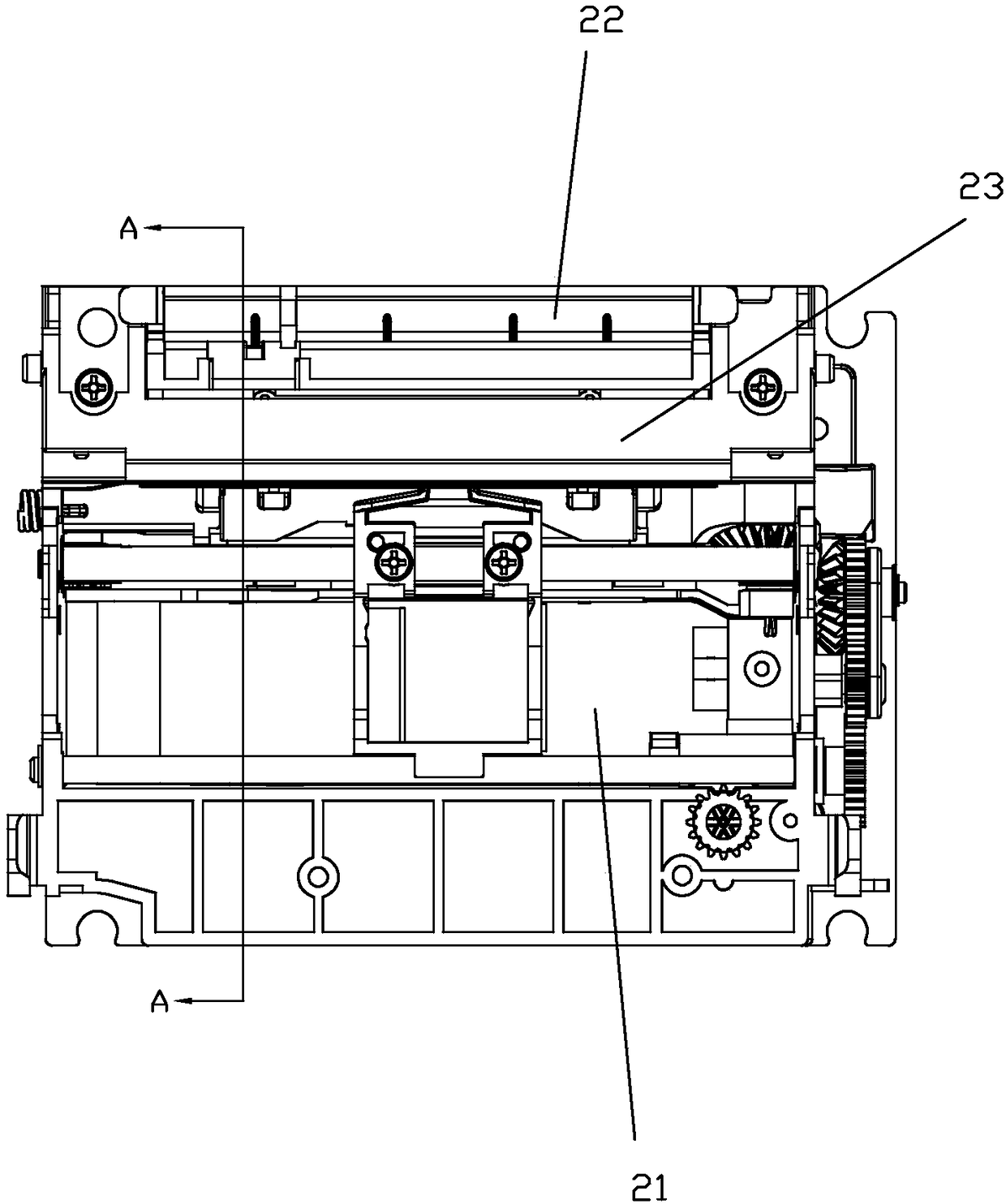
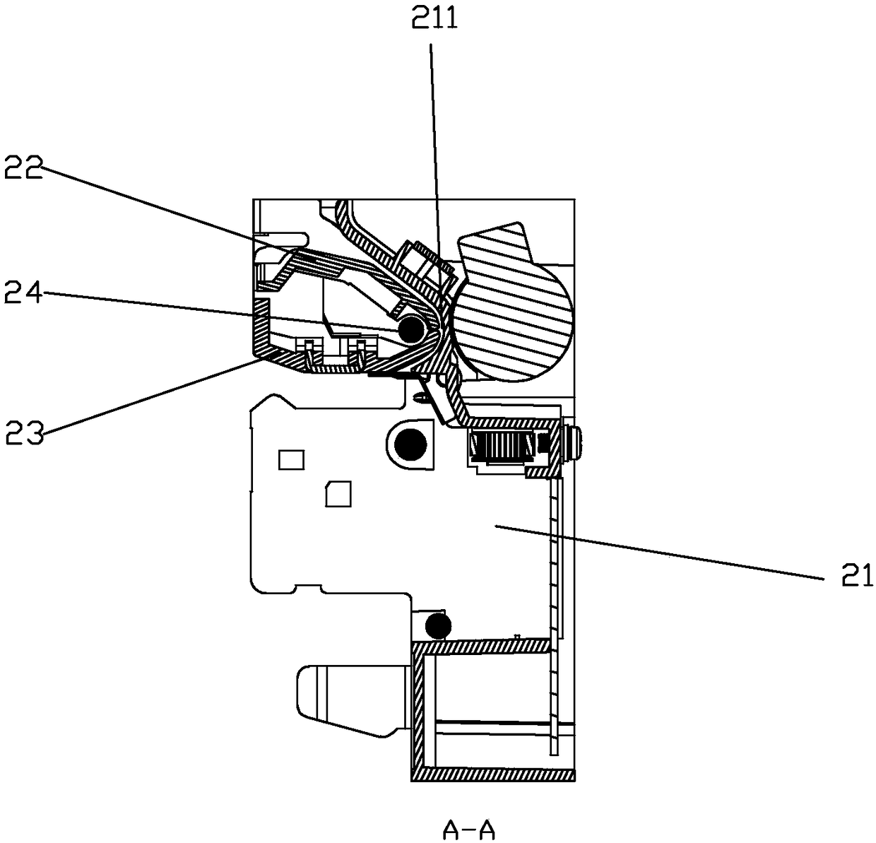
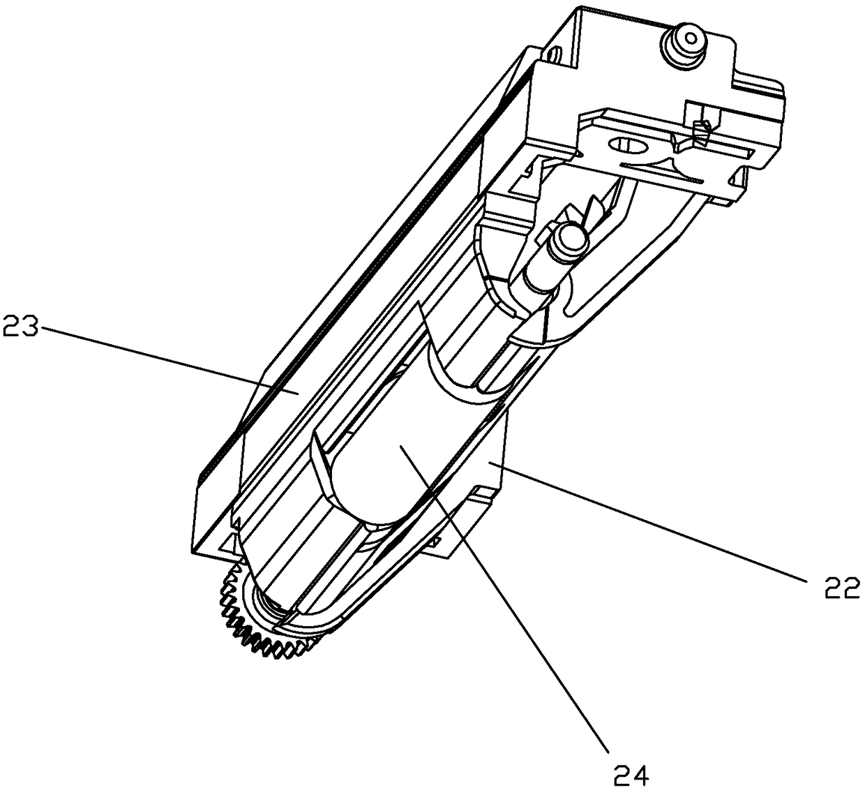
[0028] refer to figure 1 , Figure 4 , Figure 6 , Figure 7 , a micro-printer core, including an injection-molded frame 21, a curved surface groove 211 for passing paper is formed at the rear end of the frame 21, and a color ribbon device for installing a ribbon device is formed at the front end of the frame 21. With supporting frame 212, refer to figure 2 , image 3 , the curved surface groove 211 is connected with an injection-molded upper paper guide plate 22, a printing plate 23, and a paper feed roller 24, and the lower ends of the upper paper guide plate 22 and the printing plate 23 are formed to match the curved surface groove 211. After the upper paper guide plate 22 and the printing plate 23 are assembled, the lower ends of the two are attached together and a paper passage is formed between the curved surface grooves 211 . With the above-mentioned structure, the curved surface groove 211 formed on the frame 21 integrally formed by injection molding is equivalen...
PUM
Abstract
The invention discloses a miniature printer core. The miniature printer core comprises an injection-molded rack, wherein a curved surface groove used for allowing paper to pass is formed at the rear end of the rack, a colored tape support frame used for mounting a colored tape device is formed at the front end of the rack, an injection-molded upper paper guiding plate, an injection-molded printing plate and a paper feeding roller are connected to the curved surface groove, curved surfaces matched with the curved surface groove are formed at the lower ends of the upper paper guiding plate and the printing plate, the lower ends of the upper paper guiding plate and the printing plate are fitted with each other after the upper paper guiding plate and the printing plate are assembled, and a paper feeding channel is formed among the upper paper guiding plate, the printing plate and the curved surface groove. The invention provides a miniature printer which is simple in structure, simple and easy to assemble and convenient to maintain, and due to the arrangement of the fully-sealed paper feeding channel, reduces paper clamping phenomena and is convenient to clear paper.
Description
technical field [0001] The invention relates to a micro-printer core. Background technique [0002] Micro printers are widely used in various industries, such as instrumentation, supermarkets, convenience stores, postal services, banks, tobacco monopoly, utility meter reading, mobile police systems, mobile government systems, etc. Existing micro-printer cores are generally assembled with sheet metal parts, and the paper passage is formed between the lower paper guide plate, the upper paper guide plate, the printing plate, and the paper feeding roller, and the paper passage is installed on the frame. It is a sheet metal part, and the lower end is difficult to make a smooth arc surface. After assembly, there is a large gap between the upper paper guide plate and the printing plate, which may easily cause folding, twisting, or even jamming of the printing paper, which will affect the user's use. In addition, the paper passing assembly consisting of the upper paper guide plate,...
Claims
Application Information
Patent Timeline
Application Date:The date an application was filed.
Publication Date:The date a patent or application was officially published.
First Publication Date:The earliest publication date of a patent with the same application number.
Issue Date:Publication date of the patent grant document.
PCT Entry Date:The Entry date of PCT National Phase.
Estimated Expiry Date:The statutory expiry date of a patent right according to the Patent Law, and it is the longest term of protection that the patent right can achieve without the termination of the patent right due to other reasons(Term extension factor has been taken into account ).
Invalid Date:Actual expiry date is based on effective date or publication date of legal transaction data of invalid patent.
Patent Type & Authority Patents(China)
IPC IPC(8): B41J11/00B41J3/00
CPCB41J3/00B41J11/006
Inventor 吴达豪李永龙梁岐江
Owner KONG YUE ELECTRONICS & INFORMATION IND XIN HUI