
Laser marking machine

A technology of laser marking machine and laser transmitter, which is applied in the field of marking machines, can solve the problems of insufficiently stable and reliable marking quality, unreasonable and ingenious structure, and high maintenance costs, and achieve stable and reliable marking quality and stable working performance Reliable, the effect of improving the processing quality

Inactive Publication Date: 2016-12-14
东莞市环亚激光科技有限公司
View PDF12 Cites 3 Cited by
  • Summary
  • Abstract
  • Description
  • Claims
  • Application Information

AI Technical Summary

Problems solved by technology

[0003] However, the structure of laser marking machines currently on the market is not reasonable enough, resulting in large volume, complex structure, messy component layout, unreliable marking quality, low precision, low work efficiency, and high failure rate. Higher maintenance costs

Method used


Image

  • Laser marking machine
  • Laser marking machine
  • Laser marking machine

Examples


Embodiment

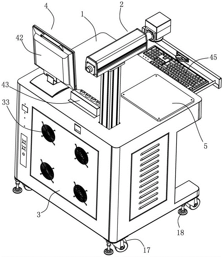
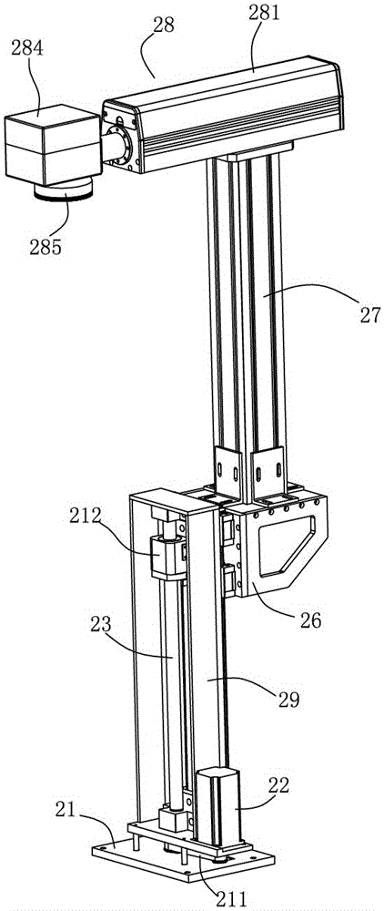
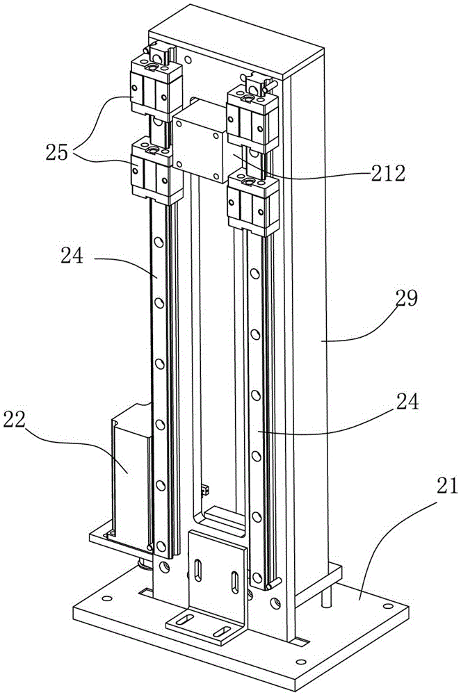
[0030] Example: such as Figure 1 to Figure 7 As shown, a laser marking machine of the present invention includes a machine platform 1, which also includes an auto-focus scanning system 2, a chassis 3 and an industrial control system 4, the chassis 3 is arranged in the machine platform 1, and the industrial control system 4 It is electrically connected with the chassis 3 and the auto-focus scanning system 2. The auto-focus scanning system 2 includes a bottom mounting plate 21, a screw 23 driven to rotate by a motor 22, a guide rail 24 arranged side by side with the screw 23, and arranged on the The slide block 25 that can move up and down on the guide rail 24, the lifting base 26 driven by the screw mandrel 23 that is fixedly connected with the slide block 25 to move up and down, the focus scanning support 27 that is arranged on the lifting base 26, and the setting The focus scanning assembly 28 on the top of the focus scanning bracket 27, the bottom mounting plate 21 is fixed...


PUM


Abstract

The invention discloses a laser marking machine. The laser marking machine comprises a machine bench, an automatic focusing and scanning system, a cabinet and an industrial control system. The cabinet is arranged in the machine bench. The industrial control system is electrically connected with the cabinet and the automatic focusing and scanning system. The automatic focusing and scanning system comprises a bottom installation plate, a screw rod, guide rails, slide blocks capable of moving up and down on the rails, an elevating base which is fixedly connected with the slide blocks and is driven by the screw rod to move up and down, a focusing and scanning support arranged on the elevating seat and a focusing and scanning assembly arranged at the top of the focusing and scanning support. The bottom installation plate is fixed in the machine bench. The focusing and scanning assembly is arranged above the machine bench. A work bench is arranged corresponding to the focusing and scanning assembly on the machine bench. The laser marking machine is simple and proper in structure, ingenuous in design, stable and reliable in working performance, high in automation degree, stable and reliable in marking quality, high in precision and efficiency, low in fault rate, and capable of effectively increasing production efficiency of an enterprise and reducing production cost.

Description

technical field [0001] The invention relates to a marking machine, in particular to a laser marking machine. Background technique [0002] Laser marking machine is to use laser beam to make permanent marks on the surface of various materials. The effect of marking is to expose the deep material through the evaporation of the surface material, so as to carve exquisite patterns, trademarks and characters. The laser marking machine is mainly divided into: CO2 laser marking machine, semiconductor laser marking machine, fiber laser marking machine And YAG laser marking machine, the current laser marking machine is mainly used in some occasions that require finer and higher precision. Used in electronic components, integrated circuits (IC), electrical appliances, mobile communications, hardware products, tool accessories, precision instruments, glasses clocks, jewelry, auto parts, plastic buttons, building materials, PVC pipes. [0003] However, the structure of laser marking ma...

Claims


Application Information

Patent Timeline
Patent Type & Authority Applications(China)
IPC IPC(8): B41J2/435
CPCB41J2/435
Inventor 王思来
Owner 东莞市环亚激光科技有限公司
Learn More