
Cone crusher

A cone crusher and cone technology, applied in the field of ore crushing, can solve the problem of inability to crush ore into small particles, and achieve the effect of high crushing ratio

Inactive Publication Date: 2016-12-14
CHENGDU DAHONGLI MACHINERY
View PDF1 Cites 5 Cited by
  • Summary
  • Abstract
  • Description
  • Claims
  • Application Information

AI Technical Summary

Problems solved by technology

[0004] Although the above-mentioned patent improves the crushing wall, the outer wall of the crushing wall and the inner wall of the body are flat slopes, which will cause the crusher to be unable to crush the ore into small particles in a short time.

Method used


Image

  • Cone crusher

Examples


Embodiment 1

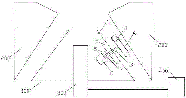
[0023] The cone crusher includes a moving cone 100, a static cone 200 is arranged outside the moving cone 100, and an eccentric bushing 300 is sleeved inside the moving cone 100, and the eccentric bushing 300 communicates with the motor 400 through a transmission device. Connected; the movable cone 100 includes a movable cone main body 1, the outer surface of the movable cone main body 1 is provided with at least one groove 2, and the bottom of the groove 2 is provided with a telescopic grinding rod 3, and the telescopic grinding rod One end of the grinding rod 3 is provided with a grinding pressing plate 4, and the other end of the telescopic grinding rod 3 is connected to the drive motor 5 located inside the moving cone main body 1, and the outer and inner surfaces of the grinding pressing plate 4 are provided with multiple grinding rods for grinding. Abrasive particles of ore6. When the ore falls from the top of the cone crusher to the upper part of the movable cone main bo...

Embodiment 2

[0025] The cone crusher includes a moving cone 100, a static cone 200 is arranged outside the moving cone 100, and an eccentric bushing 300 is sleeved inside the moving cone 100, and the eccentric bushing 300 communicates with the motor 400 through a transmission device. Connected; the movable cone 100 includes a movable cone main body 1, the outer surface of the movable cone main body 1 is provided with at least one groove 2, and the bottom of the groove 2 is provided with a telescopic grinding rod 3, and the telescopic grinding rod One end of the grinding rod 3 is provided with a grinding pressing plate 4, and the other end of the telescopic grinding rod 3 is connected to the drive motor 5 located inside the moving cone main body 1, and the outer and inner surfaces of the grinding pressing plate 4 are provided with multiple grinding rods for grinding. Abrasive particles of ore6.

[0026] The overall longitudinal section of the movable cone body 1 is fan-shaped, and the small...


PUM


Abstract

The invention relates to the technical field of ore crushing, in particular to a cone crusher. The cone crusher comprises a movable cone. A stationary cone is arranged outside the movable cone. An eccentric shaft sleeve is sleeved with the movable cone and connected with a motor through a transmission device. The movable cone comprises a movable cone body; at least one groove is formed in the outer surface of the movable cone body; an extensible grinding bar is arranged at the bottom of each groove; a grinding pressure plate is arranged at one end of each extensible grinding bar; the other end of each extensible grinding bar is connected with a drive motor located in the movable cone body; and a plurality of grinding grains used for grinding ore are arranged on the outer side face and the inner side face of each grinding pressure plate correspondingly. According to the cone crusher, the movable cone body is provided with the at least one groove and the grinding pressure plates which are matched with the grooves and have an extensible function; while the crusher is used for crushing the ore, the grinding pressure plates can be used for conducting secondary grinding on the preliminarily crushed ore, the crushed ore is made smaller, and the crushing ratio of the whole crusher is higher.

Description

technical field [0001] The invention relates to the technical field of ore crushing, in particular to a cone crusher. Background technique [0002] With the continuous development of mining technology, cone crushers are also divided into several types, including spring cone crushers, rolling cone crushers, hydraulic cone crushers and compound cone crushers according to types; PY cone crusher, Simmons cone crusher, compound cone crusher, standard hydraulic cone crusher, single-cylinder hydraulic cone crusher and multi-cylinder hydraulic cone crusher and many other models. The hydraulic crusher is developed on the basis of digesting and absorbing various types of cone crushers with international advanced level in the 1980s. It is obviously different from the structure of the traditional cone crusher in design, and has concentrated the main advantages of all types of cone crushers known so far. It is suitable for fine crushing and superfine crushing of hard rock, ore, slag, r...

Claims


Application Information

Patent Timeline
IPC IPC(8): B02C2/04
CPCB02C2/04B02C2/047
Inventor 甘德宏杨中民杨培金李海林青秋福
Owner CHENGDU DAHONGLI MACHINERY
Learn More