Slide rail with lubrication function

A technology of function and slide rail, which is applied in the field of hardware, can solve problems such as poor sliding, violent impact, and poor cushioning performance of the slide rail, and achieve the goals of avoiding poor sliding or jamming, reducing violent impact, and excellent wear resistance. Effect

Active Publication Date: 2016-12-14
HAINING JINMAO HARDWARE
View PDF7 Cites 3 Cited by
  • Summary
  • Abstract
  • Description
  • Claims
  • Application Information

AI Technical Summary

Problems solved by technology

[0004] The existing slide rail has a large contact area when sliding, so the friction force generated is also relatively large, which not only makes the slide rail wear more serious, but also produces relatively large noise, and due to the large friction force, the sliding is not smooth, and it is easy to occur Misalignment, causing misalignment and jamming, etc., which affects daily use
[0005] Unsmooth sliding is likely to cause continuous inconvenience. Due to the unsmooth sliding, users generally exert a large force when pushing and pulling, especially when closing, the cushioning performance of the slide rail is poor, which is likely to cause violent impact, resulting in relatively heavy impact. Loud noise, and it will affect the strength of the slide rail in the long run
In addition, under violent impact, the sliding rail is prone to retreat, rebound, and automatic opening, etc., often resulting in loose closing.

Method used


Image

  • Slide rail with lubrication function
  • Slide rail with lubrication function
  • Slide rail with lubrication function

Examples


Embodiment Construction

[0032] The following are specific embodiments of the present invention and in conjunction with the accompanying drawings, the technical solutions of the present invention are further described, but the present invention is not limited to these embodiments.

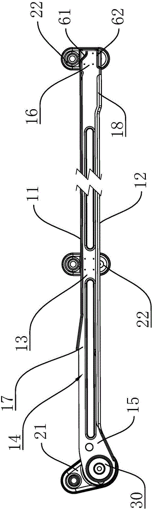
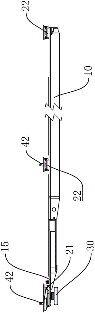
[0033] Such as Figure 1 to Figure 6 As shown, the present invention provides a slide rail with lubricating function, including a slide rail body 10, the slide rail body 10 includes an integrally formed top plate 11, bottom plate 12 and side plate 13, and the top plate 11, bottom plate 12 and side plate 13 are stamped Finally, a chute 14 for sliding guide is formed; the slide rail body 10 has a first end portion 15 and a second end portion 16, and the first end portion 15 is riveted with a fixed portion 21 for slide rail installation, and the second end portion 16 The second fixed part 22 for slide rail installation is welded, at least one fixed part two 22 is also welded between the first end part 15 and the second end pa...


PUM


Abstract

The invention discloses a slide rail with a lubrication function. The slide rail comprises a slide rail body. The slide rail body comprises a top plate, a bottom plate and side plates which are integrally formed, and a slide groove is formed after the top plate, the bottom plate and the side plates are punched; the slide rail body is provided with a first end and a second end, a first fixing portion is riveted at the first end, a second fixing portion is welded at the second end, at least one other second fixing portion is further welded between the first end and the second end, and the first fixing portion and the second fixing portions are arranged on the outer walls of the side plates; a pulley is mounted at the first end, the pulley and the first fixing portion are respectively positioned on two sides of the first end, and the pulley is movably riveted with the first fixing portion; a bumper is further mounted at the first end, and the bumper and the first fixing portion face the same side of the slide rail; abrasion-resistant layers are plated on the surfaces of the slide rail body, oil film layers are attached to the inner wall of the slide groove, oil is coated to form the oil film layers, the oil film layers are attached to the surfaces of the abrasion-resistant layers of the slide groove, an oil storage groove for oil storage and lubrication is formed in the inner wall of the bottom plate, and oil injection holes are formed in the slide rail body and are communicated with the oil storage groove.

Description

technical field [0001] The invention belongs to the technical field of hardware and relates to a slide rail, in particular to a slide rail with a lubricating function. Background technique [0002] The slide rail is a hardware connecting part fixed on the cabinet body of the furniture for the drawer or cabinet board of the furniture to move in and out. The slide rail is suitable for the drawer connection of wooden and steel drawers such as cabinets, furniture, office cabinets, and bathroom cabinets. [0003] At present, there are mainly three types of slide rails: roller type, steel ball type, and gear type. The roller type drawer slide rail has the advantages of simple structure and low noise. It is mainly composed of rollers and two rails, which can meet the daily push and pull needs. [0004] The existing slide rail has a large contact area when sliding, so the friction force generated is also relatively large, which not only makes the slide rail wear more serious, but al...

Claims


Application Information

Patent Timeline
Patent Type & Authority Applications(China)
IPC IPC(8): A47B88/04
Inventor 褚才国褚一新项炳法杜国恒蔡瑜洁赵旭
Owner HAINING JINMAO HARDWARE
Why Eureka
Try Eureka