Eureka AIR delivers breakthrough ideas for toughest innovation challenges, trusted by R&D personnel around the world.

Rotor assembly and electric driving pump

A rotor and component technology, applied in the field of centrifugal pumps, can solve the problems of high mold cost, long cycle time, waste of magnetic materials, etc., and achieve the effect of reducing mold opening costs, improving hydraulic performance, and reducing manufacturing material costs

Active Publication Date: 2016-12-07
ZHEJIANG SANHUA AUTOMOTIVE COMPONENTS CO LTD
View PDF7 Cites 9 Cited by
  • Summary
  • Abstract
  • Description
  • Claims
  • Application Information

AI Technical Summary

Problems solved by technology

[0003] The stator assembly and the rotor assembly of the electric drive pump are completely isolated by the isolation sleeve, which avoids the liquid leakage problem of the traditional motor-type brushless DC water pump; at present, the rotor assembly of the electric drive pump includes the impeller and the rotor. In the existing design, The rotor assembly is integrally formed, that is, the impeller and the rotor are injection molded from the same material, which causes a waste of magnetic materials. At the same time, for the same series of electric drive pumps with different hydraulic characteristics, the entire rotor assembly needs to be molded again, and the mold cost is high. , long cycle

Method used


Image

  • Rotor assembly and electric driving pump
  • Rotor assembly and electric driving pump
  • Rotor assembly and electric driving pump

Examples


Embodiment Construction

[0043] The present invention will be further described below in conjunction with accompanying drawing and specific embodiment:

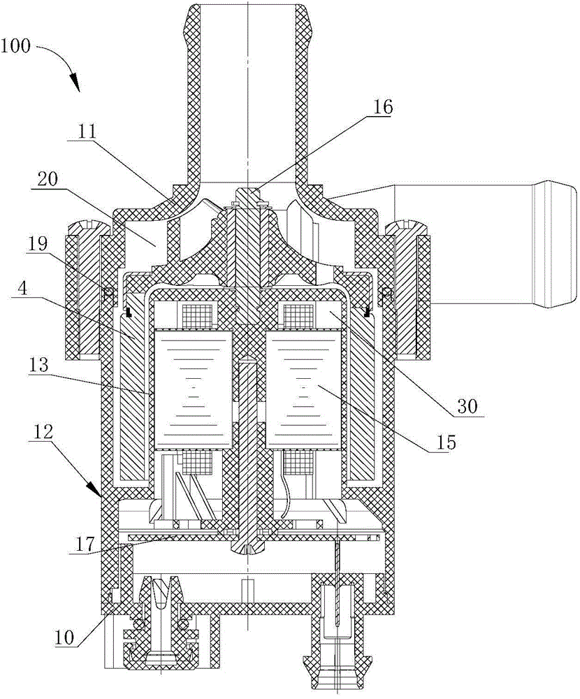
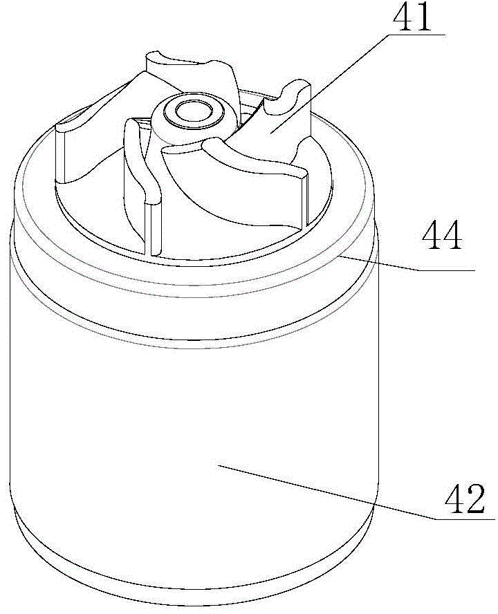
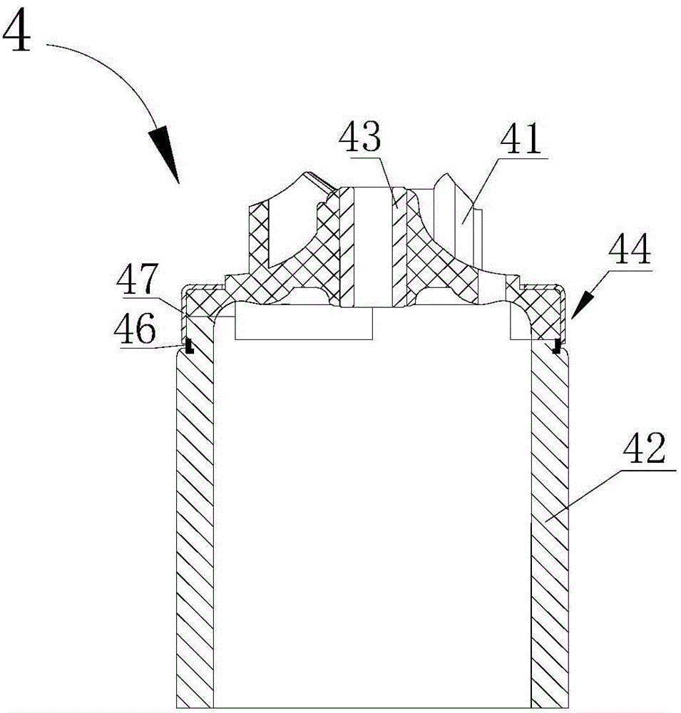
[0044] see figure 1 , the electric drive pump 100 includes a first housing 11, a second housing 12, an end cover 10, a rotor assembly 4, a stator assembly 15, a pump shaft 16, and a circuit board 17; the inner cavity of the pump includes the first housing 11, the second The space between the housing 12 and the end pipe 10, in this embodiment, the connecting part of the first housing 11 and the second housing 12 is provided with an annular sealing ring 19; the electric drive pump 100 has a spacer 13, the spacer 13 Divide the inner chamber of the pump into a flow chamber 20 and a housing chamber 30. The working medium can flow through the circulation chamber 20. The rotor assembly 4 is arranged in the circulation chamber 20. The housing chamber 30 has no working medium passing through. The stator assembly 15 and the circuit board 17 Set in the housing...


PUM


Abstract

A rotor assembly is disclosed and comprises an impeller and a rotor that are respectively and separately formed via injection mold operation; injection molding material of the rotor comprises magnetic material, injection molding material of the impeller does not comprise the magnetic material, the impeller comprises a first matching part while the rotor comprises a second matching part, the impeller and the rotor are arranged in a matched manner via the first matching part and the second matching part and are fixed relative to each other via a fixing device, and therefore the impeller and the rotor can be respectively made of different material; the impeller can be made of common plastic material, and manufacture material cost of the rotor assembly can be lowered.

Description

【Technical field】 [0001] The invention relates to a centrifugal pump, in particular to a rotor assembly of the centrifugal pump. 【Background technique】 [0002] In recent decades, the automobile industry has developed rapidly. With the performance of automobiles, it is developing in the direction of safer, more reliable, more stable, fully automatic, intelligent, environmentally friendly and energy-saving. Electric drive pumps have gradually replaced traditional mechanical pumps and are widely used in vehicle heat dissipation circulation systems. The electric drive pump has the advantages of no electromagnetic interference, high efficiency and environmental protection, stepless speed regulation, etc., which can well meet the requirements of the market. [0003] The stator assembly and the rotor assembly of the electric drive pump are completely isolated by the isolation sleeve, which avoids the liquid leakage problem of the traditional motor-type brushless DC water pump; at...

Claims


Application Information

Patent Timeline
Patent Type & Authority Applications(China)
IPC IPC(8): H02K7/14F04D13/06
CPCF04D13/0606H02K5/128H02K7/14F05D2300/43F04D13/064H02K7/085F05D2260/36F04D29/026F04D29/628F04D13/0673H02K1/2788F04D1/00F04D13/0693F04D29/043F04D29/22F04D29/426
Inventor 不公告发明人
Owner ZHEJIANG SANHUA AUTOMOTIVE COMPONENTS CO LTD
Why Eureka
Eureka Blog
Learn More