Eureka AIR delivers breakthrough ideas for toughest innovation challenges, trusted by R&D personnel around the world.

Parallel gap structure of power transmission and distribution line

A technology of transmission and distribution lines and parallel connection, which is applied in the direction of devices maintaining the distance between parallel conductors, etc., can solve problems such as low efficiency, increased use costs, and extended operating time, and achieves quick disassembly and replacement, improved performance, and reduced operating intensity. Effect

Active Publication Date: 2016-12-07
STATE GRID CORP OF CHINA +1
View PDF4 Cites 3 Cited by
  • Summary
  • Abstract
  • Description
  • Claims
  • Application Information

AI Technical Summary

Problems solved by technology

These existing structures undoubtedly have a good effect on improving the lightning protection of the arc angle. However, there is no convenient and quick way for the maintenance and replacement of the arc angle. The technicians who have overhauled the arc angle know that Due to the relatively fixed connection relationship, the existing parallel gap structure needs to replace the ball head hanging ring and the bowl head hanging ring at the same time when changing the arc angle. This method of changing the arc angle is time-consuming, laborious, inefficient, and increases Reduce the labor intensity of the operators, prolong the working time and increase the cost of use

Method used


Image

  • Parallel gap structure of power transmission and distribution line
  • Parallel gap structure of power transmission and distribution line
  • Parallel gap structure of power transmission and distribution line

Examples


Embodiment Construction

[0023] The implementation of the present invention will be illustrated by specific specific examples below, and those skilled in the art can easily understand other advantages and effects of the present invention from the contents disclosed in this specification.

[0024] Below in conjunction with accompanying drawing and embodiment the present invention will be further described:

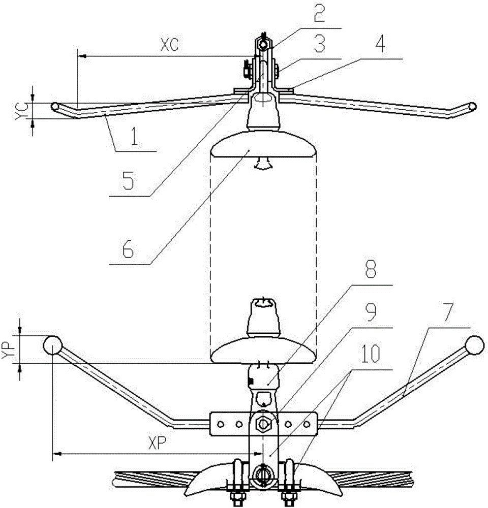
[0025] Such as figure 1 As shown, a structure of a parallel gap for transmission and distribution lines includes an upper arc angle and a lower arc angle, and the upper arc angle and the lower arc angle are respectively connected in parallel at both ends of the insulator string 6 . The upper arc angle includes the symmetrically set left and right halves of the upper arc angle 1, and similarly, the lower arc angle also includes the symmetrically set left and right halves of the lower arc angle 7, and the half upper arc angle The arc angle 1 and the lower arc angle 7 of the half are made of φ18 roun...


PUM


Abstract

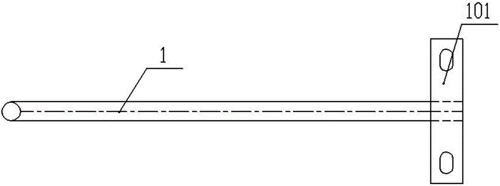
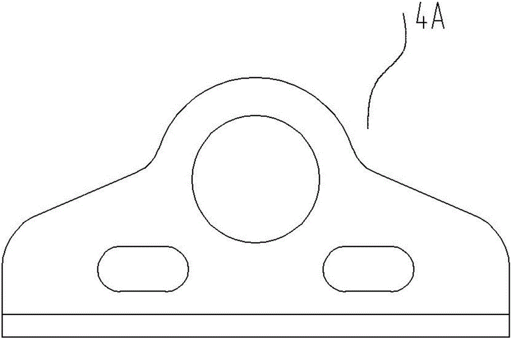
The invention discloses a parallel gap structure of a power transmission and distribution line. The parallel gap structure comprises an upper arcing horn and a lower arcing horn, wherein each of the upper arcing horn and the lower arcing horn comprises a half upper arcing horn and a half lower arcing horn which are symmetrically arranged in a left-right way, the upper arcing horn and the lower arcing horn are respectively connected in parallel to two ends of an insulator string, the half upper arcing horn is fixed on an upper arcing horn support, the upper arcing horn support has a sheet-shaped structure having an L-shaped cross section, the sheet-shaped structure is formed by two steel plates perpendicular to each other, a ball head hanging ring is arranged between the upper arcing horn supports which are symmetrically arranged, a round ring of the ball head hanging ring is parallel to vertical steel plates of the upper arcing horn supports, the ball head hanging ring is fixedly connected by the vertical steel plates perpendicularly penetrating the two upper arcing horn supports and a bolt of the round ring, a connection plate having a strip-shaped structure is fixedly arranged at an installation end of the half upper arcing horn, and each connection plate is in bolt connection with a horizontal steel plate of the upper arcing horn support. By a parallel gap, the arcing horns can be rapidly assembled and disassembled, time and labor are saved, and the labor intensity of a worker is greatly reduced.

Description

technical field [0001] The invention belongs to the protection technical field of insulators, in particular to a parallel gap structure used for lightning protection on transmission and distribution lines. Background technique [0002] The statistical data of AC high-voltage and ultra-high-voltage overhead transmission line faults in my country in recent years show that lightning strikes account for about 70% of the total line faults. Lightning discharges through insulators, and arc burns insulators, becoming permanent faults. The replacement of insulators during power outages reduces the reliability of power grid power supply and increases operating costs. At present, the existing lightning protection measures for overhead lines include: erecting lightning protection lines, reducing grounding resistance of towers, strengthening insulation, installing line-type arresters, etc. The core idea of ​​these lightning protection protection measures is to improve the lightning resis...

Claims


Application Information

Patent Timeline
IPC IPC(8): H02G7/12
CPCH02G7/12
Inventor 彭长均景蔚简泉周浩彭云竹袁永萍崔坤龙杨柳于鹏谭晓玉夏冰唐继跃
Owner STATE GRID CORP OF CHINA
Why Eureka
Eureka Blog
Learn More