
A data acquisition method and device

A data acquisition and data technology, applied in the direction of comprehensive factory control, electrical program control, comprehensive factory control, etc., can solve the problem that data cannot be collected first, cannot guarantee real-time collection, etc., and achieve the effect of fast update speed

Active Publication Date: 2018-10-19
FUJIAN LONGKING
View PDF5 Cites 0 Cited by
  • Summary
  • Abstract
  • Description
  • Claims
  • Application Information

AI Technical Summary

Problems solved by technology

However, because the upper application of the host computer has low demand for some data in all the data collected by the host computer, real-time collection is not required, and the demand for some data in all the data collected by the host computer is high, and real-time Therefore, the way the upper computer collects all the data of the underlying equipment often leads to the fact that the data with high demand of the upper application cannot be collected first, so that the real-time collection of data with high demand of the upper application cannot be guaranteed

Method used


Image

  • A data acquisition method and device
  • A data acquisition method and device
  • A data acquisition method and device

Examples


Embodiment 1

[0045] In this embodiment, a data collection method is provided, which can but is not limited to be applied to an upper computer.

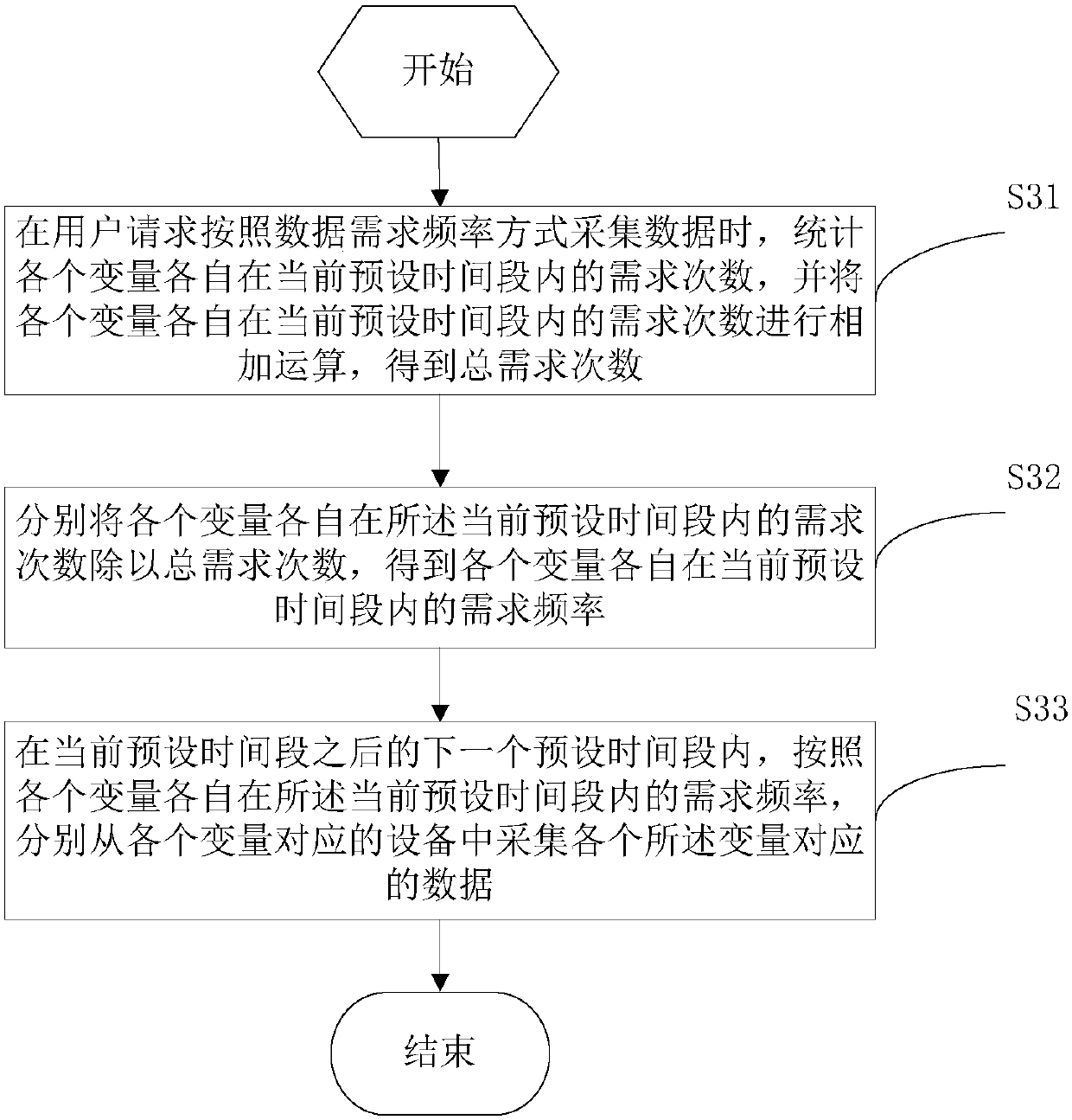
[0046] In this embodiment, when data collection is performed, data can be collected according to the data demand time mode or according to the data demand frequency mode.

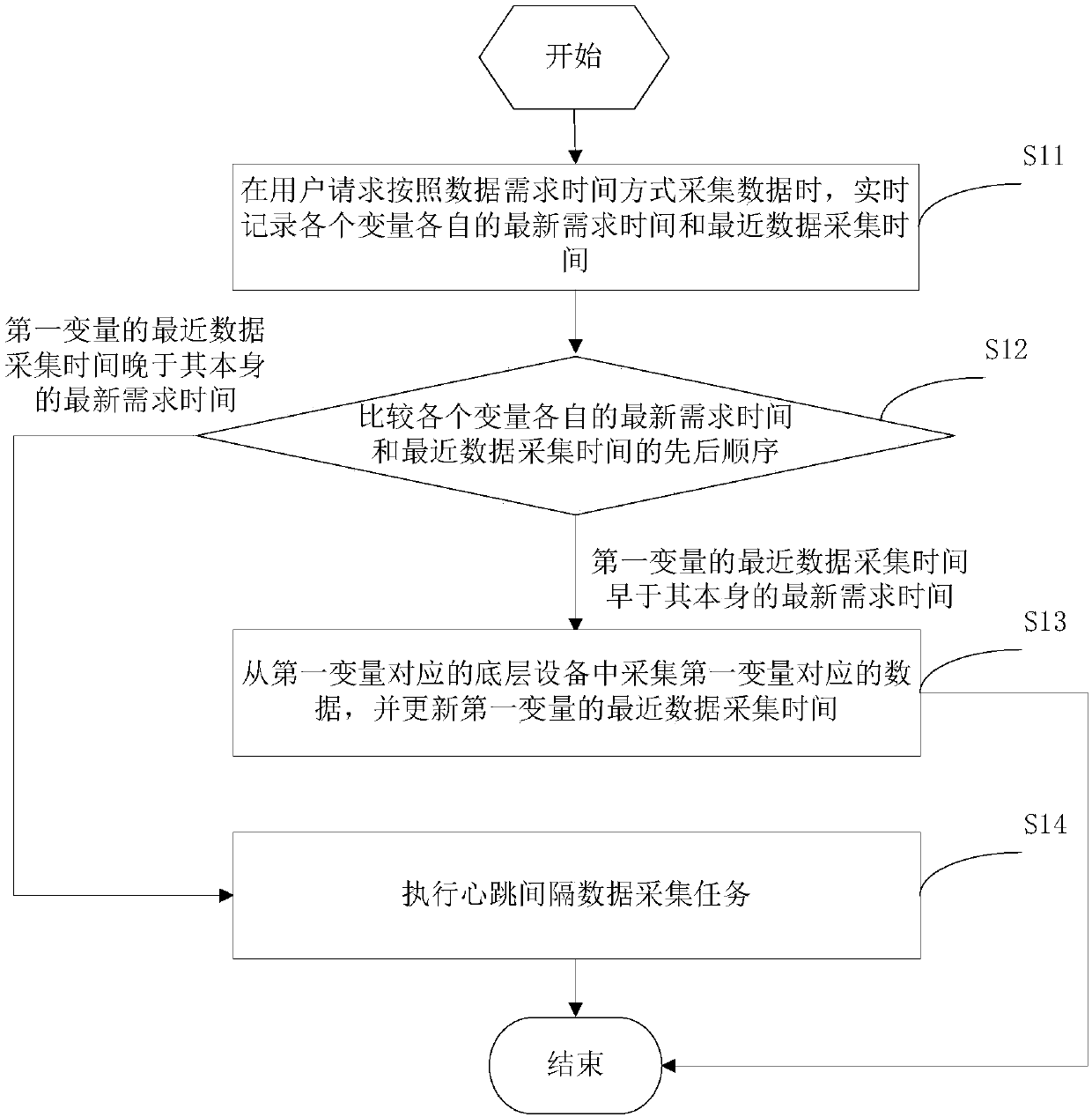
[0047] If the data is collected according to the data demand time method, please refer to the data collection process figure 1 , Which shows a flow chart of the data collection method provided by this application, which may include the following steps:

[0048] Step S11: When the user requests to collect data according to the data demand time mode, the latest demand time and the latest data collection time of each variable are recorded in real time.

[0049] The latest required time is the latest time when the host computer requests to access the variable, and the latest data collection time is the time when the host computer collects data corresponding to the variable for the last time...

Embodiment 2

[0073] In this embodiment, corresponding to the above method embodiment, this embodiment provides a data collection device, please refer to Figure 4 , The data collection device includes: a recording unit 41, a comparison unit 42, a first collection unit 43, a first update unit 44, and a first execution unit 45.

[0074] The recording unit 41 is used to record the latest demand time and the latest data collection time of each variable in real time when the user requests to collect data according to the data demand time mode. The latest demand time is the latest time when the host computer requests access to the variable. The latest data collection time is the last time the host computer collects the data corresponding to the variable.

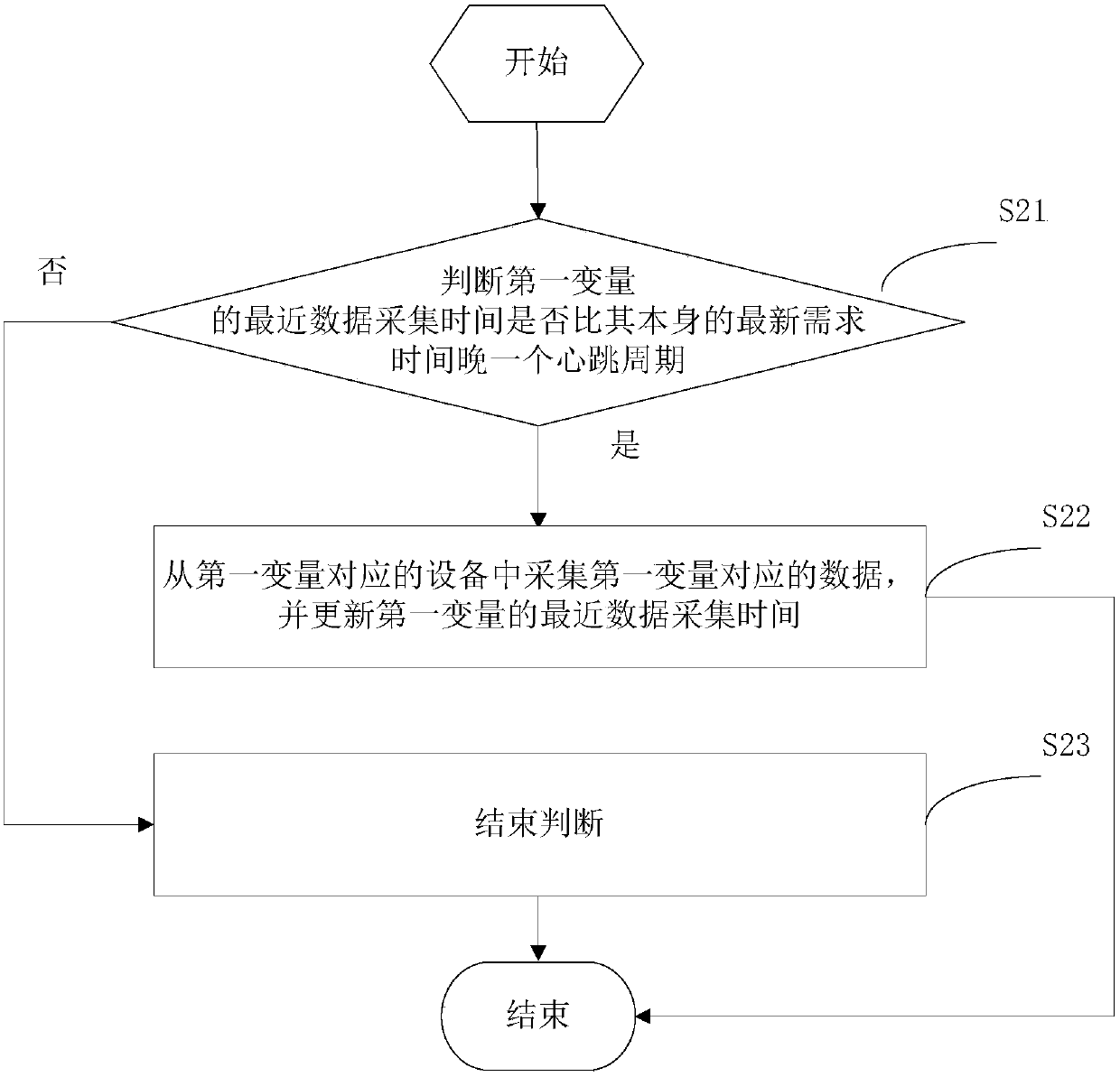
[0075] The comparison unit 42 is used to compare the sequence of the latest demand time and the latest data collection time of each of the variables, and execute the first collection unit 43 when the latest data collection time of the first variable...


PUM


Abstract

The invention provides a data collection method and device. The data collection method comprises that when a user asks to collect data according to data demand time, latest demand time and latest data collection time of each variable are recorded in real time; sequences of the latest demand time and latest data collection time of the variables are compared; when the latest data collection time of certain variable is earlier than the latest demand time of the same, data corresponding to the variable is collected from a bottom device of the variable, and the latest data collection time of the variable is updated; and when the latest data collection time of certain variable is later than the latest demand time of the same, a data collection task is executed at heartbeat interval. Thus, data corresponding to variables of higher demand degree is collected in priority, and it is ensured that data corresponding to the variables of higher demand degree is collected in real time.

Description

Technical field [0001] This application relates to the field of industrial automation, in particular to a data acquisition method and device. Background technique [0002] With the rapid improvement of industrial automation level, industrial automation systems are becoming more and more perfect. Among them, in order to ensure the normal operation of the industrial automation system, it is necessary to collect and monitor the operating data of the underlying equipment (such as PLC, smart meters, smart modules, boards, inverters, etc.) in the industrial automation system. [0003] At present, the data collection method for the bottom equipment in the industrial automation system is: communicate directly with the bottom equipment through the upper computer, and the upper computer collects all the data of the bottom equipment. However, because the upper-level application of the host computer has low demand for some data in all the data collected by the host computer, real-time collect...

Claims


Application Information

Patent Timeline
Patent Type & Authority Patents(China)
IPC IPC(8): G05B19/418
CPCY02P90/02
Inventor 吴善荣钟至光肖华生廖树锟何富昌
Owner FUJIAN LONGKING
Learn More