
Movable optical adjusting rack with lens ring adjusting function

An optical adjustment frame and mirror ring technology, applied in optics, optical components, installation, etc., can solve problems such as troublesome use and poor adjustment effect, and achieve the effects of simple use, prevention of angle deviation, and convenient operation.

Inactive Publication Date: 2016-12-07
无锡信欧光电科技有限公司
View PDF9 Cites 1 Cited by
  • Summary
  • Abstract
  • Description
  • Claims
  • Application Information

AI Technical Summary

Problems solved by technology

[0003] The object of the present invention is to provide a movable optical adjustment mount for lens ring adjustment, to solve the problem that the existing optical adjustment mount proposed in the background technology generally adjusts the adjustment mount to change the position and angle of the optical lens. Trouble, poor adjustment effect

Method used


Image

  • Movable optical adjusting rack with lens ring adjusting function
  • Movable optical adjusting rack with lens ring adjusting function
  • Movable optical adjusting rack with lens ring adjusting function

Examples


Embodiment Construction

[0014] The following will clearly and completely describe the technical solutions in the embodiments of the present invention with reference to the accompanying drawings in the embodiments of the present invention. Obviously, the described embodiments are only some, not all, embodiments of the present invention. Based on the embodiments of the present invention, all other embodiments obtained by persons of ordinary skill in the art without making creative efforts belong to the protection scope of the present invention.

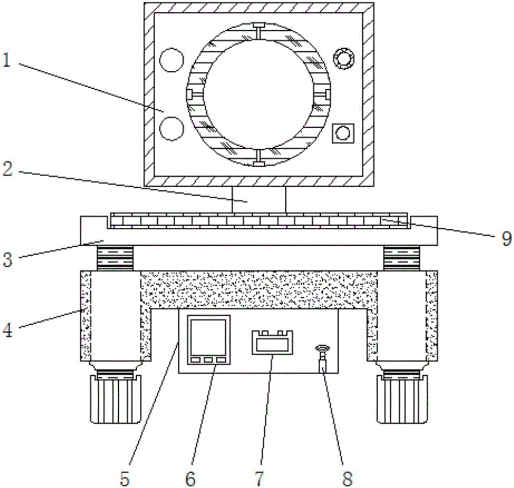
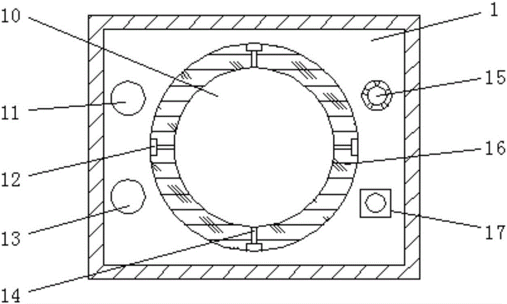
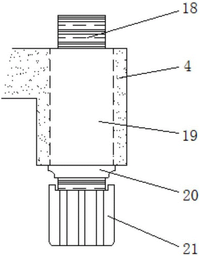
[0015] see Figure 1-3 , an embodiment provided by the present invention: a movable optical adjustment frame for mirror ring adjustment, including a fixed mirror frame 1, a movable plate 3 and a fixed base 4, an upper and lower angle adjustment knob 11 is fixed above one end of the fixed mirror frame 1, And the left and right angle adjustment knobs 13 are fixed below the up and down angle adjustment knobs 11, the rotating shaft locking button 15 is fixed above...


PUM


Abstract

The invention discloses a movable optical adjusting rack with a lens ring adjusting function. The movable optical adjusting rack comprises a fixing lens bracket, a movable plate and a fixing base. A lens ring is fixed in the middle of the fixing lens bracket and comprises an angle rotating shaft and a transmission rod, an optical lens is fixed in the middle of the lens ring, the movable plate is installed below the fixing lens bracket, and the fixing base is installed below the movable plate. Fixing holes are formed in the two ends in the fixing base, horizontal adjusting screws are fixed in the fixing holes, the upper ends of the horizontal adjusting screws are connected with the movable plate, and horizontal adjusting knobs are fixed to the lower ends of the horizontal adjusting screws. A case is fixed to the lower end of the middle of the fixing base, a wireless signal receiving and transmitting device is fixed in the case, and a storage battery is installed on one side of the wireless signal receiving and transmitting device. According to the movable optical adjusting rack, a movable lens ring adjusting mode is adopted, the angle of the optical lens can be adjusted through the angle rotating shaft and the transmission rod in the lens ring, and the movable optical adjusting rack is easy to use and convenient to control.

Description

technical field [0001] The invention relates to the technical field of optical adjustment mount equipment, in particular to a movable optical adjustment mount for mirror ring adjustment. Background technique [0002] The optical adjustment mount is a very important device in the use of optical instruments. The quality of the optical adjustment mount directly affects the working quality of the optical instrument. However, the existing optical adjustment mounts generally adjust the adjustment mounts to change the The position and angle of the optical lens are cumbersome to use and the adjustment effect is poor. Contents of the invention [0003] The object of the present invention is to provide a movable optical adjustment mount for lens ring adjustment, to solve the problem that the existing optical adjustment mount proposed in the background technology generally adjusts the adjustment mount to change the position and angle of the optical lens. Trouble, the problem of poor...

Claims


Application Information

Patent Timeline
Patent Type & Authority Applications(China)
IPC IPC(8): G02B7/00
CPCG02B7/00
Inventor 杨向通
Owner 无锡信欧光电科技有限公司
Learn More