
Gas-liquid separator and heat pump unit comprising same

A gas-liquid separator and separation chamber technology, applied in compressors, refrigerators, refrigeration components, etc., can solve the problems of compressor refrigeration system damage, liquid liquid hammer, liquid refrigerant entering, etc., to speed up the separation speed, improve the The effect of purity

Inactive Publication Date: 2016-12-07
CHONGQING MIDEA GENERAL REFRIGERATING EQUIP +1
View PDF11 Cites 8 Cited by
  • Summary
  • Abstract
  • Description
  • Claims
  • Application Information

AI Technical Summary

Problems solved by technology

When the amount of liquid refrigerant exceeds the upper critical point of the U-tube, a large amount of liquid refrigerant will enter the compressor when the unit is turned on, causing serious liquid shock phenomenon, which will cause great damage to the compressor itself and the refrigeration system;

Method used


Image

  • Gas-liquid separator and heat pump unit comprising same
  • Gas-liquid separator and heat pump unit comprising same
  • Gas-liquid separator and heat pump unit comprising same

Examples


specific Embodiment approach

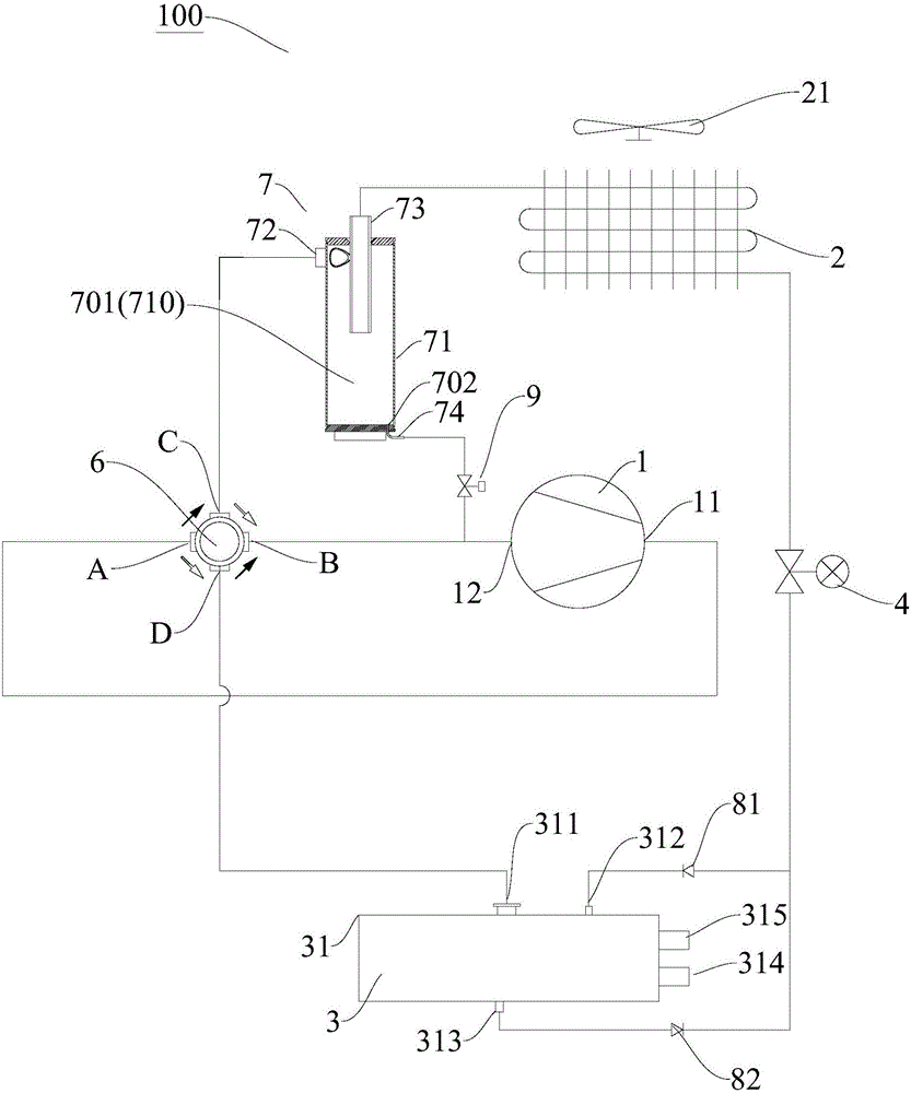
[0095] When the unit is running for refrigeration, the cycle flow is: compressor 1 → four-way valve → multi-functional gas-liquid separator 7 → fin heat exchangerelectronic expansion valve → water side heat exchanger → four-way valve → compressor 1. When the unit is running for heating, the cycle flow is: compressor 1 → four-way valve → water side heat exchanger → electronic expansion valve → fin heat exchanger → multifunctional gas-liquid separator 7 → four-way valve → compressor 1.

[0096] The main working principle of this system is: the multifunctional gas-liquid separator 7 is placed between the finned heat exchanger of the heat pump unit 100 and the four-way valve. During defrosting or cooling operation (working according to the refrigeration cycle flow), the high-temperature refrigerant exhausted from compressor 1 enters the fin heat exchanger through multi-functional gas-liquid separator 7 for defrosting, and the separated lubricating oil returns to the return circu...


PUM


Abstract

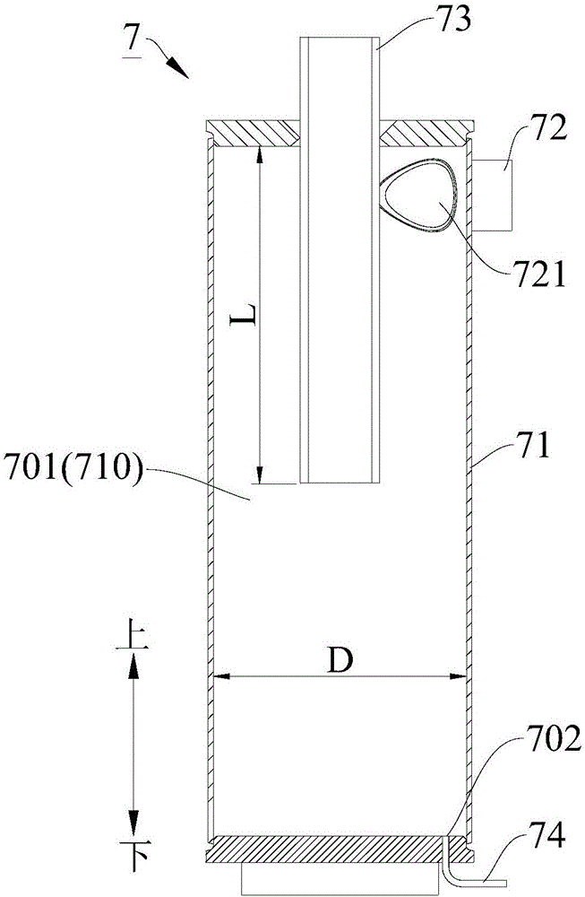
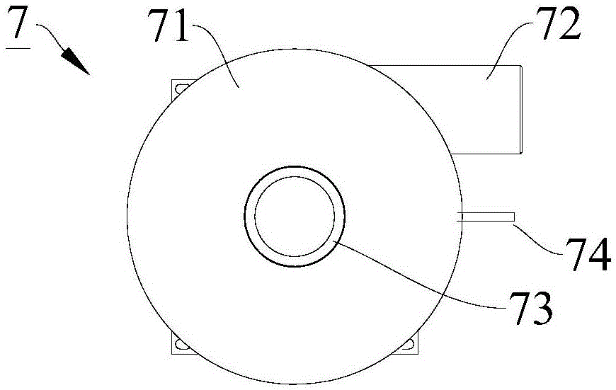
The invention discloses a gas-liquid separator and a heat pump unit comprising the same. The gas-liquid separator comprises a casing, a first inlet / outlet pipe and a second inlet / outlet pipe; an inner cavity of the casing comprises a separation cavity; the separation cavity forms a rotating cavity extending vertically along an axis; an oil return port communicating with the separation cavity is formed in the bottom end of the casing; the first inlet / outlet pipe and the second inlet / outlet pipe are connected onto the casing; the first inlet / outlet pipe communicates with the separation cavity in the tangential direction to form a communicating port; the second inlet / outlet pipe extends into the inner cavity from the top end of the casing; and an opening, extending into the inner cavity, of the second inlet / outlet pipe is located below the communicating port. According to the gas-liquid separator, liquid oil drops in an oil-gas mixture are suitable to flow in the first inlet / outlet pipe when separated, so that the purity of a separated gaseous refrigerant can be improved; and a liquid refrigerant contained in a gas-liquid mixture is suitable to flow into the second inlet / outlet pipe when the liquid refrigerant is relatively many, thus, the separation speed can be increased, and the gas-liquid separator further has multiple functions during practical application.

Description

technical field [0001] The invention relates to the field of refrigeration and heating equipment, in particular to a gas-liquid separator and a heat pump unit having the same. Background technique [0002] For the gas-liquid separator used in the heat pump system, the second inlet and outlet pipes are usually U-shaped, the gas-liquid mixture enters from the straight pipe inlet, and is discharged from the U pipe after gas-liquid separation. A small amount of liquid can pass through the return pipe at the lower part of the U pipe. The oil port and the gas are discharged from the U pipe together to prevent a large amount of liquid from entering the compressor. There are still some shortcomings and deficiencies in the use of traditional gas-liquid separators, as follows: [0003] a. When the heat pump unit is defrosting in the reverse cycle, a large amount of liquid refrigerant is condensed and stored in the fin heat exchanger. After the defrosting is completed, the refrigerant...

Claims


Application Information

Patent Timeline
IPC IPC(8): F25B43/02F25B31/00
CPCF25B43/02F25B31/004
Inventor 张洪亮李超牟珊珊
Owner CHONGQING MIDEA GENERAL REFRIGERATING EQUIP
Learn More