
Temperature control low-nitrogen and energy-saving combustion device capable of achieving flue gas recirculation and staged premixed combustion

A premixed combustion and combustion device technology, applied in the direction of gas fuel burners, burners, combustion methods, etc., can solve the problems of unreasonable use of energy and turning a blind eye

Active Publication Date: 2016-12-07
陈维汉
View PDF6 Cites 12 Cited by
  • Summary
  • Abstract
  • Description
  • Claims
  • Application Information

AI Technical Summary

Problems solved by technology

There are many low-grade energy sources with exhaust gas temperature below 200°C. They are reluctant to give up and use large investment to apply them, but they turn a blind eye to the temperature difference of 200°C and above in the high temperature section, so that the energy cannot be used rationally. So how to achieve the combustion temperature? It is an urgent problem to be solved at present to make full use of the heat at the high-temperature end while reasonably controlling it, so as to save fuel, save costs and suppress the formation of nitrogen oxides.

Method used


Image

  • Temperature control low-nitrogen and energy-saving combustion device capable of achieving flue gas recirculation and staged premixed combustion
  • Temperature control low-nitrogen and energy-saving combustion device capable of achieving flue gas recirculation and staged premixed combustion

Examples


Embodiment Construction

[0008] The specific embodiments of the present invention will be described in detail below with reference to the accompanying drawings.

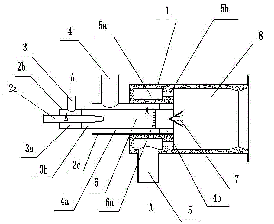
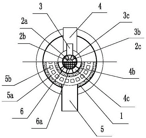
[0009] Such as figure 1 and figure 2 As shown, the present invention includes a combustion chamber 1 with one end closed and one end open. The open end of the combustion chamber has a mixed combustion space 8 built in. One end of the mixed combustion space is closed and the other end is open. The open end of the mixed combustion space and the opening of the combustion chamber The open end of the combustion chamber is the air flow outlet. The closed end of the mixed combustion space has a staged combustor extending through the closed end of the combustion chamber into the combustion chamber and connected with the mixed combustion space. The staged burner passes through the closure of the combustion chamber. The end that extends into the combustion chamber is the inner end, and the other end is the outer end. The closed end of the combustion cha...


PUM


Abstract

The invention relates to a temperature control low-nitrogen and energy-saving combustion device capable of achieving flue gas recirculation and staged premixed combustion. The combustion device can effectively complete airflow straight flow or rotational flow staged premixing and combustion, the combustion temperature is lowered, the content of nitrogen oxide can be effectively controlled, gas consumption is reduced, and energy saving is realized. A mixed combustion space is arranged in the opening end of a combustion chamber. The closed end of the mixed combustion space is connected with a staged combustor. A recirculation flue gas inlet pipe is arranged on the outer circle of a recirculation flue gas distribution loop in the closed end of the combustion chamber. Recirculation flue gas bleeding pipes are arranged between the recirculation flue gas distribution loop and the mixed combustion space. Supporting spinning disks are arranged in each loop of the staged combustor. An airflow adjusting blunt body is arranged at the opening of the inner end of the staged combustor. Primary and secondary air inlet pipes are arranged on the side wall of the staged combustor. An aided mixing flow equalizing plate is arranged in a primary air pre-mixing chamber in the opening of the inner end of the staged combustor. The temperature control low-nitrogen and energy-saving combustion device is more obvious in energy-saving effect, the combustion temperature and nitrogen oxide production are effectively controlled, and pollution to the atmospheric environment is reduced.

Description

Technical field [0001] The invention relates to a combustion device for heat utilization equipment of industrial furnaces, and is particularly suitable for use in industrial furnaces such as boilers, heating furnaces, hot blast furnaces, metal smelting furnaces, rotary kilns, tunnel kilns, shuttle kilns, etc. that burn gas fuel. A temperature-controlled, low-nitrogen and energy-saving combustion device with flue gas reflux and staged premixed combustion. Background technique [0002] At present, industrial furnaces and kilns consider energy saving and environmental protection, and require the combustion device to obtain efficient and controllable complete combustion under the combustion of different fuels and different coal gas, while also requiring effective reduction of the formation of nitrogen oxides (NOx) during the combustion process. In order to achieve the goal of high efficiency, energy saving and environmental protection. For this reason, in the structural design of in...

Claims


Application Information

Patent Timeline
IPC IPC(8): F23D14/02F23D14/62F23D14/70F23L9/00
CPCF23D14/02F23D14/62F23D14/70F23L9/00
Inventor 陈维汉陈云鹤杨海涛张佳鹏
Owner 陈维汉
Learn More