
Invisible-light lamp bead with lighting scope marking function

A technology of luminous range and visible light, applied in the field of ultraviolet LEDs, can solve the problem of not being able to know the luminous range of invisible light, and achieve the effect of preventing UV accidental injury

Active Publication Date: 2016-12-07
QINGDAO JASON ELECTRIC
View PDF5 Cites 11 Cited by
  • Summary
  • Abstract
  • Description
  • Claims
  • Application Information

AI Technical Summary

Problems solved by technology

[0004] This application provides an invisible light bead that can mark the luminous range, which solves the technical problem that the luminous range of invisible light cannot be known in the prior art

Method used


Image

  • Invisible-light lamp bead with lighting scope marking function
  • Invisible-light lamp bead with lighting scope marking function
  • Invisible-light lamp bead with lighting scope marking function

Examples


Embodiment Construction

[0022] The specific implementation manners of the present application will be described in further detail below in conjunction with the accompanying drawings.

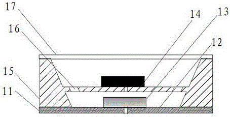
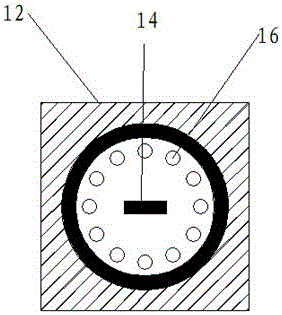
[0023] Such as figure 1 As shown, the invisible light lamp bead that can mark the luminous range proposed by this application includes a first bracket, a second bracket 12, an indicator light 13 and an invisible light lamp bead 14; the second bracket is surrounded by bracket side walls 15; A support 11 is fixedly connected up and down with the second support 12, so that the upper surface of the first support 11, the support side wall 15 (in the figure, a part of the support side wall 15 is located at the lower side of the second support, and a part is located at the upper side of the second support) and A cavity is formed between the lower surfaces of the second bracket.

[0024] The indicator light is fixed on the upper surface of the first support; specifically, the circuit wiring is printed on the surface of the fi...


PUM


Abstract

The invention discloses an invisible-light lamp bead with a lighting scope marking function, and aims to solve the technical problem that the lighting scope of invisible light cannot be acquired. The invisible-light lamp bead comprises a first bracket, a second bracket, an indicator, an invisible-light lamp beam body and a bracket side wall connected with the periphery of the second bracket, wherein the first bracket and the second bracket are fixedly connected in an up-down manner, thereby forming a cavity among the upper surface of the first bracket, the bracket side wall, and the lower surface of the second bracket; the indicator and the invisible-light lamp beam body are respectively fixed on the upper surfaces of the first bracket and the second bracket; light channels are formed in the second bracket and around the invisible-light lamp beam body; light emitted from the indicator passes the light channels, and then light spots are formed around the invisible-light lamp beam body; and an annular light ring is formed from the light spots and used for marking the lighting scope of the invisible-light lamp beam body. According to the invisible-light lamp bead disclosed by the invention, the lighting scope of invisible-light can be marked by visible light emitted from the indicator, thereby achieving the technical effect of marking the lighting scope of invisible-light.

Description

technical field [0001] The invention belongs to the technical field of ultraviolet LEDs, and in particular relates to an invisible light lamp bead capable of marking a luminous range. Background technique [0002] The ultraviolet light emitted by the ultraviolet LED has a wavelength of 10nm-400nm in the electromagnetic spectrum, which cannot cause people's vision and belongs to invisible light. Ultraviolet rays are absorbed through the skin, which can damage DNA (deoxyribonucleic acid). When DNA is damaged, cells will die or develop into uncontrolled cancer cells. It can be seen that ultraviolet energy has a great destructive effect, but people are sensitive to ultraviolet rays. The luminous range of LED and understand. [0003] Alternatively, when the ultraviolet LED is used for the sterilization performance, especially under the action of strong light, since people cannot accurately know its working range, the use effect of the ultraviolet LED with the sterilization perfo...

Claims


Application Information

Patent Timeline
Patent Type & Authority Applications(China)
IPC IPC(8): F21K9/23F21V7/22F21V21/00F21V23/00F21Y115/10
CPCF21V7/22F21V21/00F21V23/00
Inventor 白生茂万永泉曲丞世张晓裴潘娜王洁武帅张国华周德宝
Owner QINGDAO JASON ELECTRIC
Learn More