
Coiled tubing falling-prevention device and usage method thereof

An anti-dropping and tubing technology, applied in drilling pipe, casing, earth-moving drilling, etc., can solve the problems of coiled tubing falling into the well, blowout out of control, coiled tubing loosening, etc., achieving easy processing and assembly, and convenient use and operation , the effect of high work efficiency

Active Publication Date: 2016-12-07
BC P INC CHINA NAT PETROLEUM CORP +1
View PDF10 Cites 12 Cited by
  • Summary
  • Abstract
  • Description
  • Claims
  • Application Information

AI Technical Summary

Problems solved by technology

[0002] In the production and development process of various oil and gas fields, the most common construction of coiled tubing is to carry out operations such as gas lift injection, sand washing and plug removal in 2 7 / 8″ or 3 1 / 2″ tubing, and sometimes coiled tubing After being broken off, it got stuck in the tubing, and the broken coiled tubing could not be fished out by conventional fishing methods. The coiled tubing could only be taken out by the tubing. After the coiled tubing is stuck in the tubing, the remaining dropped coiled tubing can be pulled out by drilling the special clip for the coiled tubing at the wellhead and penetrating the injection head. The stuck point of the coiled tubing becomes loose, causing the risk of the coiled tubing falling into the well again. At the same time, the inner cavity of the coiled tubing at the wellhead and the space between the coiled tubing and the small annulus of the tubing are in an uncontrolled state, and the risk of well control is great. Once an overflow occurs, etc. Well control is dangerous, failure to take effective measures is likely to cause blowout or blowout out of control accidents, so it is necessary to develop a device to solve the above problems

Method used


Image

  • Coiled tubing falling-prevention device and usage method thereof
  • Coiled tubing falling-prevention device and usage method thereof
  • Coiled tubing falling-prevention device and usage method thereof

Examples


Embodiment approach

[0033] The embodiment of a coiled tubing anti-drop device of the present invention is as follows:

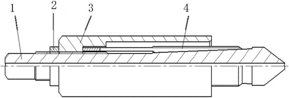
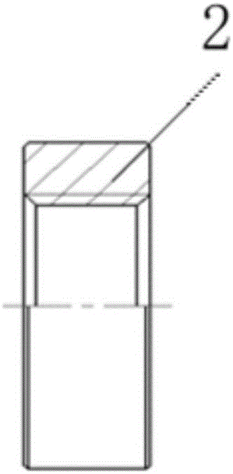
[0034] Before field use, complete the assembly of the coiled tubing drop prevention device according to the instructions: first, insert the slotted slip 4 from the upper end of the spear-shaped central rod 1, and then insert the spear-shaped central rod 1 into the limit protection tube 3 Inside, after adjusting the relative position of the spear-shaped central rod 1 and the limit protection tube 3 through the screw thread on the spear-shaped central rod 1, screw the back cap 2 on the upper part of the spear-shaped central rod 1 and tighten it, that is, assemble Finished coiled tubing drop prevention device.

[0035] When the coiled tubing is working in the tubing, and it breaks off for some reason and gets stuck in the tubing, the broken coiled tubing cannot be fished out with conventional fishing tools, and the coiled tubing can only be taken out by pulling the tubing. The coi...


PUM


Abstract

The invention discloses a coiled tubing falling-prevention device and a usage method thereof. The coiled tubing falling-prevention device comprises a spear-shaped central rod, a grooving slip and a limiting prevention cylinder which are sequentially arranged from inside to outside in a sleeved mode. The inner wall of the limiting prevention cylinder sequentially and inward sinks from top to bottom step by step to form a first annular step and a second annular step which are in shapes of steps, the top end face of the grooving slip abuts against the lower end face of the first annular step, an outer thread is arranged on the outer wall of the spear-shaped central rod, a connecting outer thread is arranged on the inner wall of the first annular step of the limiting prevention cylinder, and the grooving slip is limited by adjusting the limiting prevention cylinder relative to the position at the thread connecting position on the spear-shaped central rod. A falling-prevention function during coiled tubing fishing can be played by using the coiled tubing falling-prevention device. When a dangerous overflow case appears at a well opening, blowout prevention short section matched with the device is rapidly installed in time, and the blowout prevention problem of a coiled tubing inner cavity and a small annulus between the coiled tubing and an oil pipe can be also solved.

Description

technical field [0001] The invention relates to the technical field of oil and gas field exploitation, in particular to a device for preventing falling of a coiled tubing and an application method thereof. Background technique [0002] In the production and development process of various oil and gas fields, the most common construction of coiled tubing is to carry out operations such as gas lift injection, sand washing and plug removal in 2 7 / 8″ or 3 1 / 2″ tubing, and sometimes coiled tubing After being broken off, it got stuck in the tubing, and the broken coiled tubing could not be fished out by conventional fishing methods. The coiled tubing could only be taken out by the tubing. After the coiled tubing is stuck in the tubing, the remaining dropped coiled tubing can be pulled out by drilling the special clip for the coiled tubing at the wellhead and penetrating the injection head. The stuck point of the coiled tubing becomes loose, causing the risk of the coiled tubing fa...

Claims


Application Information

Patent Timeline
IPC IPC(8): E21B17/02E21B33/06E21B17/043E21B19/10
Inventor 吴德傅小勇任勇强王风锐王辉武宗刚崔世杰刘华贾小琴张国华
Owner BC P INC CHINA NAT PETROLEUM CORP
Learn More