
Gantry elevator with followup end plates

A lift and gantry-type technology, which is applied in the field of gantry-type lifts, can solve problems such as low efficiency, unstable support reliability, and unfavorable vehicle chassis support, and achieve the effect of large support area and increased support reliability

Active Publication Date: 2016-12-07
TIANJIN SAIXIANG M&E ENG CO LTD
View PDF6 Cites 2 Cited by
  • Summary
  • Abstract
  • Description
  • Claims
  • Application Information

AI Technical Summary

Problems solved by technology

[0003] The lifting arm of the gantry lift used to hold up the locomotive is the same as that of the double-column lift. They are two lifting arms that can rotate left and right. There is no blocking structure around the pallet for the rotating lift arm, which is not conducive to the support of the car chassis, and every time it is supported, it is necessary to adjust the support position of the lift arm, which is inefficient and unstable in support reliability

Method used


Image

  • Gantry elevator with followup end plates

Examples


Embodiment Construction

[0014] In order to make the technical means, creative features, goals and effects achieved by the present invention easy to understand, the present invention will be further elaborated below.

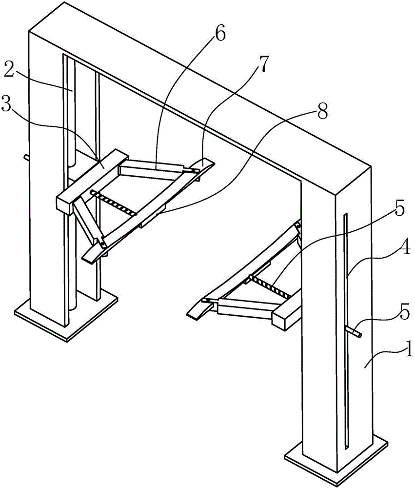
[0015] Such as figure 1 As shown, the gantry lift with follow-up end plate 7 includes two stands 1, each of which is provided with a lifting screw 2, and the lifting screws 2 are equipped with lifting The base frame 3 and the lower end of the lifting screw 2 are connected to a motor for driving the corresponding lifting screw 2 through a gear connection, and a beam is connected to the upper end of the stand 1 together.

[0016] The side of the stand 1 away from the other stand 1 is provided with a vertical strip hole 4, and a horizontal push screw 5 that can move up and down in the strip hole 4 is pierced in the strip hole 4. , the two ends of the lifting base frame 3 away from the corresponding stand 1 are fixedly connected with a lifting arm 6, and the lifting arm 6 is a secondary te...


PUM


Abstract

The invention relates to a gantry elevator with followup end plates. The gantry elevator comprises two vertical frames; lifting screw rods are respectively arranged in the vertical frames, and are both coated with lifting base frames; the lower ends of the lifting screw rods are connected with motors through a gear connecting mode; the upper ends of the vertical frames are connected with a cross beam; the side surface, far from the other vertical frames, of the vertical frames are provided with vertical strip holes; transverse pushing screw rods are inserted in the strip holes; two end parts, far from one sides of the corresponding vertical frames, of the lifting base frames are fixedly connected with lifting arms; the lifting arms are two-grade extension arms; end plates are mounted at the other ends of the two lifting arms mounted on the same one lifting base frames; one end parts of the transverse pushing screw rods are movably clamped on the end plates on the corresponding sides; and the transverse pushing screw rods can rotate corresponding to the end plates. The gantry elevator adopts the lifting arms incapable of rotating to lift, matches the lifting arms with the end plates connected to the end parts of the lifting arms to form stable triangular structures, and guarantees no accidental steering of the lifting arms during lifting.

Description

technical field [0001] The invention relates to the technical field of lifting equipment, in particular to a gantry-type lift with a follow-up end plate. Background technique [0002] The gantry lift is one of the most commonly used lifts. Since the upper end of the gantry lift is supported by a beam, it can effectively offset the torque of the lift frame and ensure the overall force balance and support stability of the lift. . [0003] The lifting arm of the gantry lift used to hold up the locomotive is the same as that of the double-column lift. They are two lifting arms that can rotate left and right. There is no blocking structure around the tray for the rotating lift arm, which is not conducive to the support of the car chassis, and every time it is supported, the support position of the lift arm needs to be adjusted, which is inefficient and unstable in support reliability. Contents of the invention [0004] In view of the above defects, the present invention propo...

Claims


Application Information

Patent Timeline
Patent Type & Authority Applications(China)
IPC IPC(8): B66F7/06B66F7/28
CPCB66F7/0608B66F7/28
Inventor 李明忠徐峰
Owner TIANJIN SAIXIANG M&E ENG CO LTD
Learn More