
Buffering decelerating device of overturning mechanism of spacecraft

A technology of deceleration device and turning mechanism, which is applied in the direction of space navigation equipment, space navigation aircraft, aircraft, etc., can solve the problems of weakened deceleration effect of broken rope, inappropriate turning speed change, small applicable range of broken rope, etc., to achieve Expand the scope of application, improve environmental adaptability and reliability, and achieve better deceleration effect

Active Publication Date: 2016-12-07
SHENZHEN GRADUATE SCHOOL TSINGHUA UNIV
View PDF4 Cites 1 Cited by
  • Summary
  • Abstract
  • Description
  • Claims
  • Application Information

AI Technical Summary

Problems solved by technology

[0002] In the existing spacecraft overturning mechanism, broken ropes, rubber pads and honeycomb cushions are usually used as the buffer deceleration devices; when the buffer deceleration device of the spacecraft overturning mechanism adopts broken ropes, since the broken ropes pass through the control force When the turning speed of the spacecraft turning mechanism fluctuates greatly, in order to make the turning arm rotate normally, the turning arm can also break the broken rope at the minimum speed, that is, the broken rope can only be broken according to the rotation of the turning arm. The lower limit design, but when the speed fluctuates greatly and the speed is large, the deceleration effect of the broken rope is greatly weakened, so the applicable range of the broken rope is small, and it is not suitable for the working condition with a large change in the turning speed; when the buffer of the spacecraft turning mechanism When the deceleration device uses rubber pads or honeycomb buffer pads, it is difficult to control the thickness change after impact due to the rubber pads and honeycomb buffer pads have certain elasticity, so it is difficult to guarantee the positioning accuracy of the turning mechanism

Method used


Image

  • Buffering decelerating device of overturning mechanism of spacecraft
  • Buffering decelerating device of overturning mechanism of spacecraft

Examples


Embodiment Construction

[0023] The present invention will be further described below with reference to the accompanying drawings and in combination with preferred embodiments.

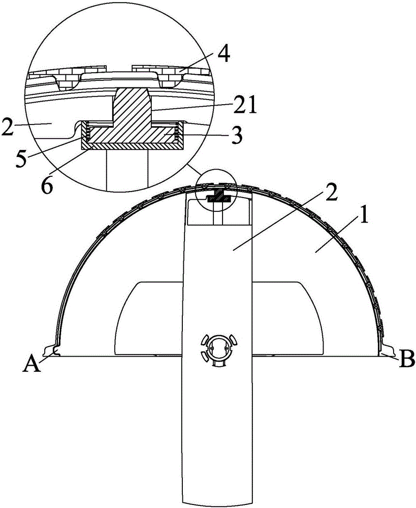
[0024] Such as figure 1 and figure 2 As shown, it is a schematic diagram of a spacecraft turning mechanism comprising a buffer deceleration device according to a preferred embodiment of the present invention. The spacecraft turning mechanism also includes a frame shell 1 and a rotating arm 2. The frame shell 1 is a semicircular structure, and the rotating arm 2 It is a circular motion mechanism, which is rotatably connected to the frame shell 1; the buffer deceleration device includes a deceleration adjustment block 3 and a plurality of deceleration blocks 4, and a plurality of deceleration blocks 4 are installed on the frame shell 1, and the deceleration adjustment block 3 can be moved along the It is installed on the rotating arm 2 to move radially. When the rotating arm 2 rotates, the deceleration adjustment block 3 will...


PUM


Abstract

The invention discloses a buffering decelerating device of an overturning mechanism of a spacecraft. The overturning mechanism of the spacecraft comprises a machine frame housing and a rotor arm, wherein the machine frame housing adopts a semicircle structure; the rotor arm is rotatably connected to the machine frame housing; the buffering decelerating device comprises a decelerating adjusting block and one or more decelerating baffle plates; the decelerating baffle plates are mounted on the machine frame housing; the decelerating adjusting block can be movably mounted on the rotor arm in a radial direction; and the decelerating adjusting block can extend the rotor arm under the effect of the centrifugal force to be in matching contact with the decelerating baffle plates. Through the adoption of the buffering decelerating device of the overturning mechanism of the spacecraft disclosed by the invention, not only working conditions of which the rotating speed of the overturning mechanism of the spacecraft is greatly changed can be adapted, but also the targeting accuracy of the overturning mechanism of the spacecraft is not influenced.

Description

technical field [0001] The invention relates to the application field of spacecraft, in particular to a buffer and deceleration device for a turning mechanism of a spacecraft. Background technique [0002] In the existing spacecraft overturning mechanism, broken ropes, rubber pads and honeycomb cushions are usually used as the buffer deceleration devices; when the buffer deceleration device of the spacecraft overturning mechanism adopts broken ropes, since the broken ropes pass through the control force When the turning speed of the spacecraft turning mechanism fluctuates greatly, in order to make the turning arm rotate normally, the turning arm can also break the broken rope at the minimum speed, that is, the broken rope can only be broken according to the rotation of the turning arm. The lower limit design, but when the speed fluctuates greatly and the speed is large, the deceleration effect of the broken rope is greatly weakened, so the applicable range of the broken rope...

Claims


Application Information

Patent Timeline
Patent Type & Authority Applications(China)
IPC IPC(8): B64G1/22
CPCB64G1/22
Inventor 梁斌李成王学谦雷纲王培明李郑发
Owner SHENZHEN GRADUATE SCHOOL TSINGHUA UNIV
Learn More